Atmega128rfa1 – Rainbow Electronics ATmega128RFA1 User Manual
Page 172
172
8266A-MCU Wireless-12/09
ATmega128RFA1
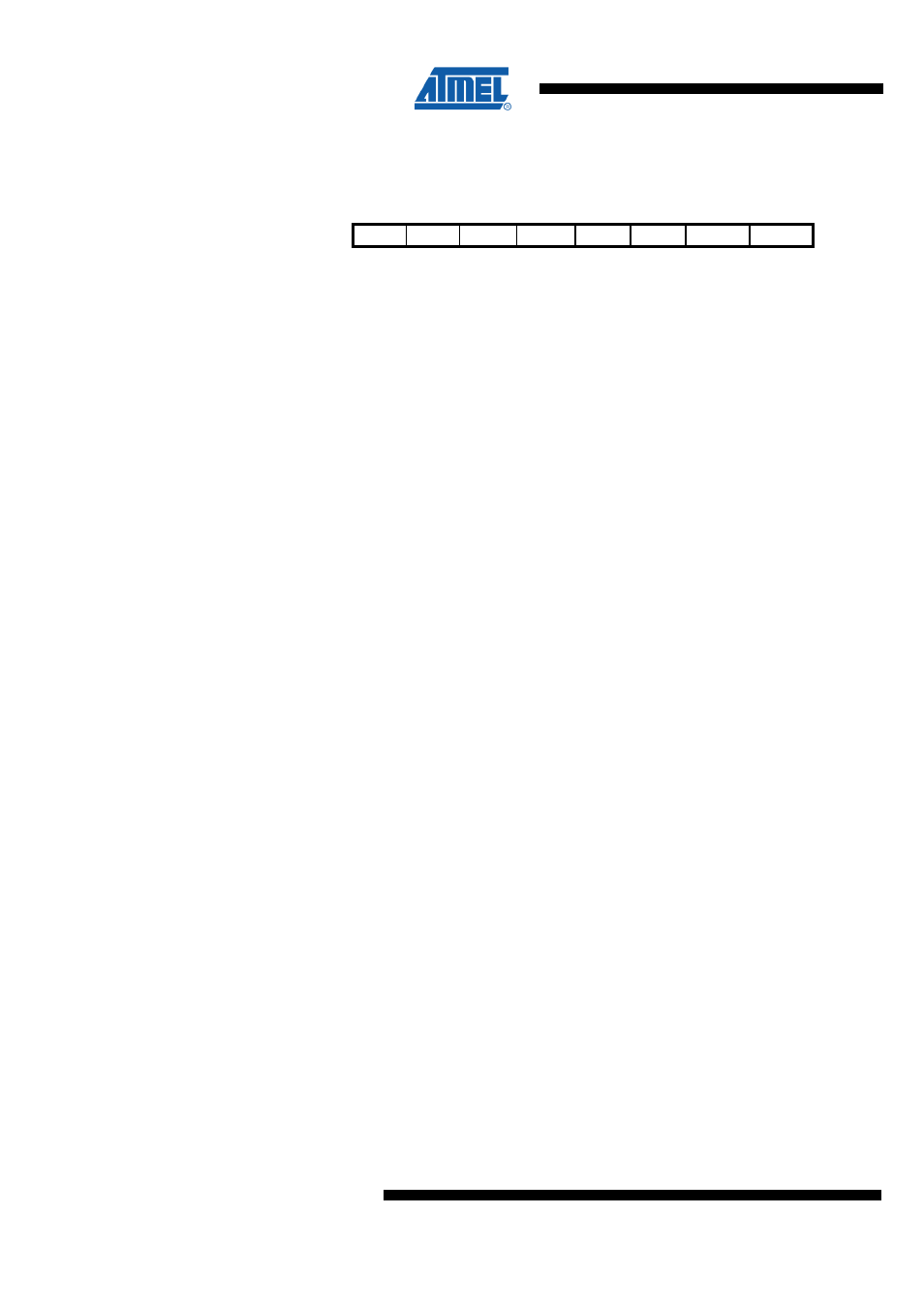
12.6.10 LLCR – Low Leakage Voltage Regulator Control Register
Bit
7
6
5
4
3
2
1
0
NA ($12F)
Res1
Res0
LLDONE LLCOMP LLCAL
LLTCO LLSHORT LLENCAL
LLCR
Read/Write
R
R
R
R
R
RW
RW
RW
Initial Value
0
0
0
0
0
0
0
1
This register allows to monitor and to control the calibration process of the low-leakage
voltage regulator. The automatic calibration is the normal operation mode. However,
certain circumstances may require to disable this automatic process for instance to
save power-up time. The results of the automatic calibration can also be modified when
required by the application for instance to get a higher or lower output voltage.
•
Bit 7:6 – Res1:0 - Reserved Bit
This bit is reserved for future use. A read access always will return zero. A write access
does not modify the content.
•
Bit 5 – LLDONE - Calibration Done
This bit indicates the last state of the calibration algorithm. The data register contents is
updated with new calibration data after the bit changed to 1. The bit will only be high for
one 64kHz clock period, because a new calibration loop is started automatically.
•
Bit 4 – LLCOMP - Comparator Output
This bit indicates the output state of the comparator of the low-leakage voltage
regulator. In this way the calibration progress can be directly monitored for debug
purposes. The state of the bit changes at most every 64kHz clock period.
•
Bit 3 – LLCAL - Calibration Active
This bit indicates that the automatic calibration is in progress. The analog part of the
calibration circuit is powered up if the bit is 1.
•
Bit 2 – LLTCO - Temperature Coefficient of Current Source
This bit shows the status of the selection of the temperature coefficient. The state of the
bit is updated in the course of the automatic calibration. A valid value is present after
the LLDONE bit is 1 for the first time. Write access is only enabled when the automatic
calibration is turned off (LLENCAL is 0). This bit should not be changed without further
information.
•
Bit 1 – LLSHORT - Short Lower Calibration Circuit
This bit shows the status of the short switch for the lower calibration circuit. The state of
the bit is updated in the course of the automatic calibration. A valid value is present
after the LLDONE bit is 1 for the first time. If this bit is set to 1 register LLDRL has no
function. Write access is only possible when the automatic calibration is turned off
(LLENCAL is 0). This bit should not be changed without further information.
•
Bit 0 – LLENCAL - Enable Automatic Calibration
This bit enables the automatic calibration. The automatic calibration runs if the state of
the bit is 1. Write access to the two data register and the bits LLSHORT and LLTCO is
then denied. If the state of LLENCAL is 0 then the calibration algorithm is stopped and
the output voltage of the low-leakage voltage regulator is defined by the values in the
two data register LLDRL and LLDRH and by the bits LLSHORT and LLTCO.