11 register description, 1 sccnthh - symbol counter register hh-byte, Atmega128rfa1 – Rainbow Electronics ATmega128RFA1 User Manual
Page 137
137
8266A-MCU Wireless-12/09
ATmega128RFA1
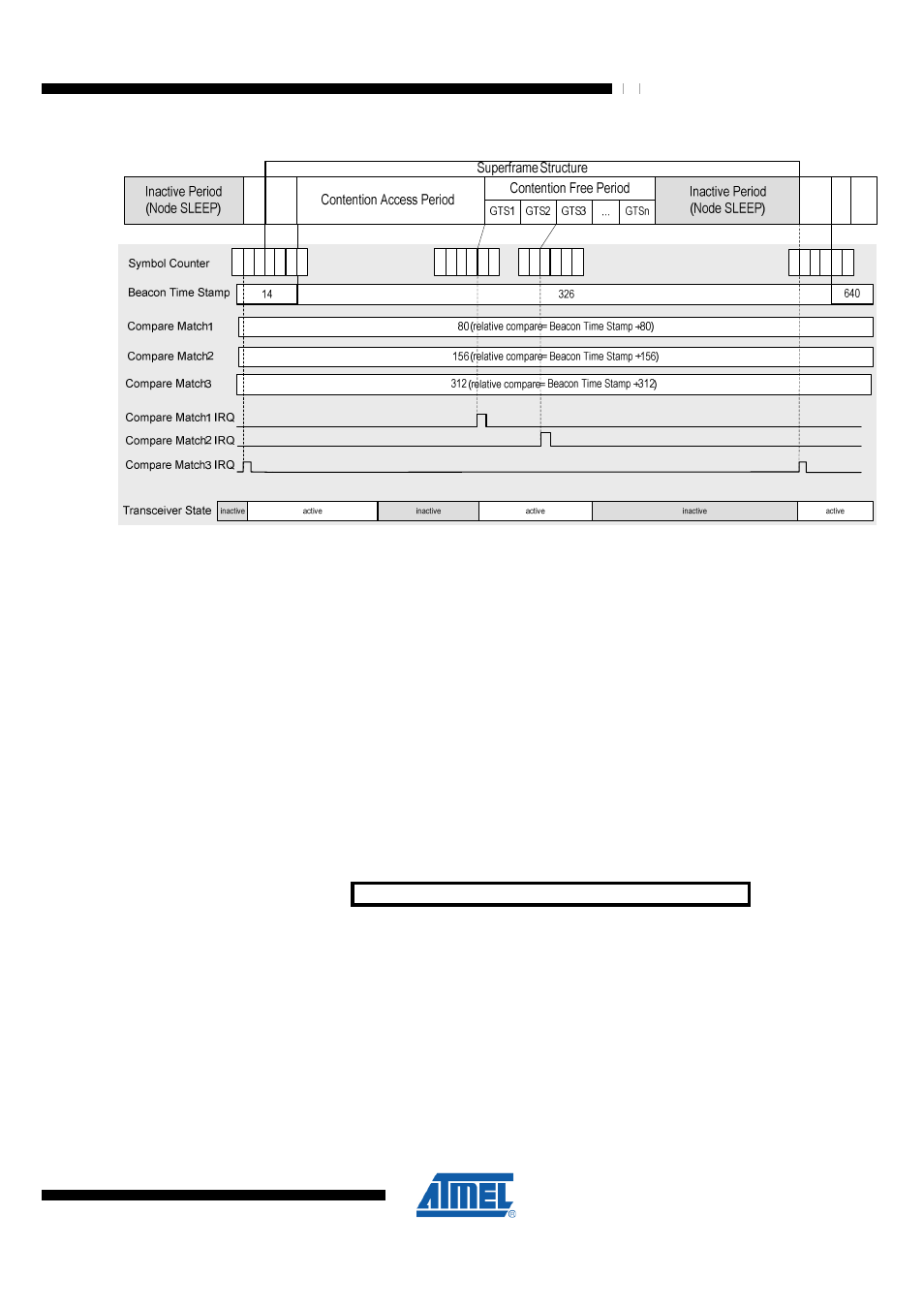
Figure 10-2. Relative Compare Mode
3
2
6
B
e
a
c
o
n
B
e
a
c
o
n
3
2
7
3
2
8
3
2
9
3
2
4
3
2
5
4
0
4
4
0
5
4
0
6
4
0
7
4
0
2
4
0
3
4
8
2
4
8
3
4
8
4
4
8
5
4
8
0
4
8
1
6
3
7
6
3
8
6
4
0
6
4
1
6
3
5
6
3
6
3
2
3
A
c
ti
v
a
ti
o
n
A
c
ti
v
a
ti
o
n
The compare match registers are programmed with symbol intervals relative to the
beacon frame SFD timestamp. For instance the SCCMP1 is programmed to 80,
because the first Granted Time Slot (GTS1) is expected 80 symbols after the beacon
frame. Register SCCMP2 is programmed to 156 to meet GTS3 156 symbols after the
beacon frame. SCCMP3 is programmed to 312. This is the time interval where the
beacon of the next superframe is expected. Because it requires some time to activate
the transceiver and there is also some timing drift possible, the compare interrupt must
be programmed to wake up some symbols in advance to make sure the next beacon is
not missed.
If the controller receives a compare match wake up event it is activating the transceiver.
After the frame operations are finished, the system can go back to sleep until the next
compare match event occurs.
10.11 Register Description
10.11.1 SCCNTHH – Symbol Counter Register HH-Byte
Bit
7
6
5
4
3
2
1
0
NA ($E4)
SCCNTHH7:0
SCCNTHH
Read/Write
RW
RW
RW
RW
RW
RW
RW
RW
Initial Value
0
0
0
0
0
0
0
0
This register contains the most significant byte of the 32 bit Symbol Counter.
•
Bit 7:0 – SCCNTHH7:0 - Symbol Counter Register HH-Byte