2 general circuit description, Atmega128rfa1 – Rainbow Electronics ATmega128RFA1 User Manual
Page 30
30
8266A-MCU Wireless-12/09
ATmega128RFA1
The ATmega128RFA1 features a low-power 2.4 GHz radio transceiver designed for
industrial and consumer ZigBee/IEEE 802.15.4, 6LoWPAN, RF4CE and high data rate
2.4 GHz ISM band applications. The radio transceiver is a true peripheral block of the
AVR microcontroller. All RF-critical components except the antenna, crystal and de-
coupling capacitors are integrated on-chip. Therefore, the ATmega128RFA1 is
particularly suitable for applications like:
•
2.4 GHz IEEE 802.15.4 and ZigBee systems
•
6LoWPAN and RF4CE systems
•
Wireless sensor networks
•
Industrial control, sensing and automation (SP100, WirelessHART)
•
Residential and commercial automation
•
Health care
•
Consumer electronics
•
PC peripherals
9.2 General Circuit Description
This radio transceiver is part of a system-on-chip solution with an AVR
®
microcontroller.
It comprises a complex peripheral component containing the analog radio, digital
modulation and demodulation including time and frequency synchronization and data
buffering. The number of external components for the transceiver operation is
minimized such that only the antenna, the crystal and decoupling capacitors are
required. The bidirectional differential antenna pins (RFP, RFN) are used for
transmission and reception, thus no external antenna switch is needed.
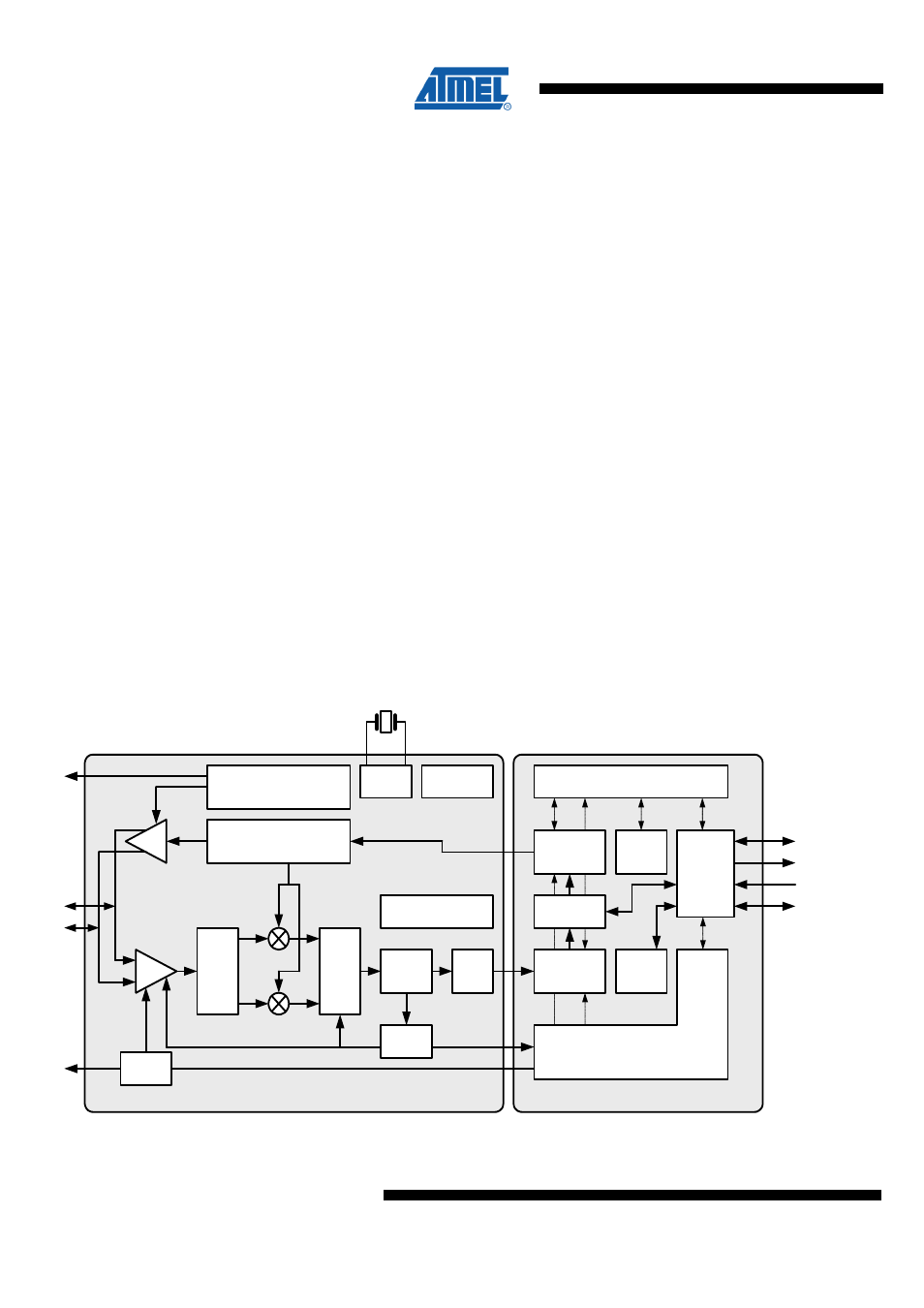
The ATmega128RFA1 block diagram is shown in
.
Figure 9-9. Transceiver Block Diagram
AVREG
LNA
PLL
PA
PPF
BPF
Limiter
RX
ADC
AGC
ext. PA and Power
Control
Configuration Registers
µC
Interface
RSSI
Data
Interrupts
Address
Control
DIG3/4
RFP
RFN
TX Data
Control Logic
Antenna Diversity
FTN, BATMON
XOSC
X
T
A
L
1
X
T
A
L
2
Analog Domain
Digital Domain
AES
DIG1/2
AD
DVREG
RX BBP
Frame
Buffer
TX BBP