12 programming algorithm, 13 entering programming mode, 14 leaving programming mode – Rainbow Electronics ATmega128RFA1 User Manual
Page 489: Atmega128rfa1
489
8266A-MCU Wireless-12/09
ATmega128RFA1
During Page Read, the content of the selected Flash byte is captured into the Flash
Data Byte Register during the Capture-DR state. The AVR automatically alternates
between reading the low and the high byte for each new Capture-DR state, starting with
the low byte for the first Capture-DR encountered after entering the
PROG_PAGEREAD command. The Program Counter is post-incremented after reading
each high byte, including the first read byte. This ensures that the first data is captured
from the first address set up by PROG_COMMANDS, and reading the last location in
the page makes the program counter increment into the next page.
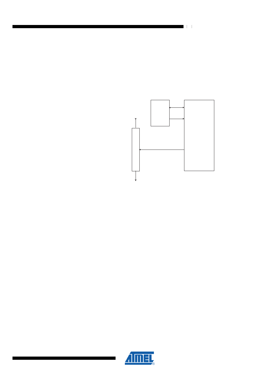
Figure 31-20. Flash Data Byte Register
TDI
TDO
D
A
T
A
Flash
EEPROM
Fuses
Lock Bits
STROBES
ADDRESS
State
Machine
The state machine controlling the Flash Data Byte Register is clocked by TCK. During
normal operation in which eight bits are shifted for each Flash byte, the clock cycles
needed to navigate through the TAP-controller automatically feeds the state machine
for the Flash Data Byte Register with sufficient number of clock pulses to complete its
operation transparently for the user. However, if too few bits are shifted between each
Update-DR state during page load, the TAP-controller should stay in the Run-Test/Idle
state for some TCK cycles to ensure that there are at least 11 TCK cycles between
each Update-DR state.
31.9.12 Programming Algorithm
All references below of type “1a”, “1b”, and so on, refer to
31.9.13 Entering Programming Mode
1. Enter JTAG instruction AVR_RESET and shift 1 in the Reset Register.
2. Enter instruction PROG_ENABLE and shift 0b1010_0011_0111_0000 in the
Programming Enable Register.
31.9.14 Leaving Programming Mode
1. Enter JTAG instruction PROG_COMMANDS.
2. Disable all programming instructions by using no operation instruction 11a.
3. Enter instruction PROG_ENABLE and shift 0b0000_0000_0000_0000 in the
programming Enable Register.
4. Enter JTAG instruction AVR_RESET and shift 0 in the Reset Register.