2 clock characteristics, 1 calibrated internal rc oscillator accuracy, 2 external clock drive – Rainbow Electronics ATmega128RFA1 User Manual
Page 502: 3 system and reset characteristics, Clock, System and reset, Atmega128rfa1
502
8266A-MCU Wireless-12/09
ATmega128RFA1
34.2 Clock Characteristics
34.2.1 Calibrated Internal RC Oscillator Accuracy
Table 34-2. Calibration Accuracy of Internal RC Oscillator
Frequency
V
DEVDD
Temperature
Calibration Accuracy
Factory Calibration
16 MHz
3.0V
25°C
± TBD %
User Calibration
TBD
1.8V – 3.6V
-TBD°C - TBD°C
± TBD %
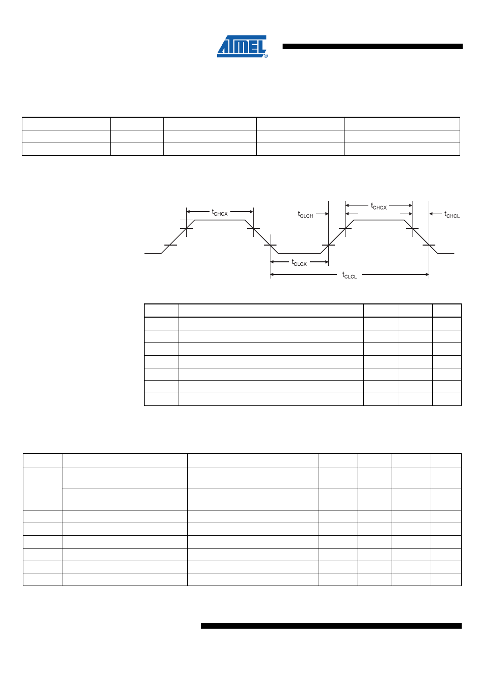
34.2.2 External Clock Drive
Figure 34-1 External Clock Drive Waveforms
V
IL1
V
IH1
Table 34-3. External Clock Drive
Symbol Parameter
Min.
Max.
Units
1/t
CLCL
Oscillator Frequency
16
MHz
t
CLCL
Clock Period
62.5
ns
t
CHCX
High Time
25
ns
t
CLCX
Low Time
25
ns
t
CLCH
Rise Time
0.1
µs
t
CHCL
Fall Time
0.1
µs
∆
t
CLCL
Change in period from one clock cycle to the next
1
%
34.3 System and Reset Characteristics
Table 34-4. Reset, Brown-out and Internal Voltage Characteristics
Symbol
Parameter
Condition
Min
Typ
Max
Units
Power-on Reset Threshold Voltage
(rising)
TBD
V
V
POT
Power-on Reset Threshold Voltage
(falling)
(
1
)
0.3
V
V
PSR
Power-on slope rate
TBD
V/ms
V
RST
RSTN Pin Threshold Voltage
0.2V
DEVDD
0.9V
DEVDD
V
t
RST
Minimum pulse width on RSTN Pin
TBD
ns
V
HYS
Brown-out Detector Hysteresis
50
mV
t
BOD
Min Pulse Width on Brown-out Reset
100
ns
V
BG
Bandgap reference voltage
V
DEVDD
= 3.0V, T
A
= 25°C
1.2
V
Note:
1. The Power-on Reset will not work unless the supply voltage has been below V
POT
(falling).