1 reusing the temporary high byte register, 4 timer/counter clock sources, 5 counter unit – Rainbow Electronics ATmega128RFA1 User Manual
Page 249: Atmega128rfa1
249
8266A-MCU Wireless-12/09
ATmega128RFA1
C Code Examples
(1)
void TIM16_WriteTCNTn( unsigned int i )
{
unsigned char sreg;
unsigned int i;
/* Save global interrupt flag */
sreg = SREG;
/* Disable interrupts */
__disable_interrupt();
/* Set TCNTn to i */
TCNTn = i;
/* Restore global interrupt flag */
SREG = sreg;
}
Notes:
1. See
"About Code Examples" on page 7
18.3.1 Reusing the Temporary High Byte Register
If writing to more than one 16-bit register where the high byte is the same for all
registers written, then the high byte only needs to be written once. However note that
the same rule of atomic operation described previously also applies in this case.
18.4 Timer/Counter Clock Sources
The Timer/Counter can be clocked by an internal or an external clock source. The clock
source is selected by the Clock Select logic which is controlled by the Clock Select
(CSn2:0) bits located in the Timer/Counter control Register B (TCCRnB). For details on
clock sources and prescaler, see
"Timer/Counter 0, 1, 3, 4, and 5 Prescaler" on page
.
18.5 Counter Unit
The main part of the 16-bit Timer/Counter is the programmable 16-bit bi-directional
counter unit. The following figure shows a block diagram of the counter and its
surroundings.
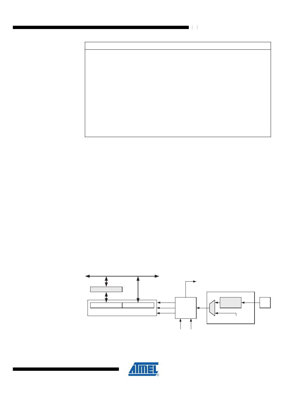
Figure 18-2. Counter Unit Block Diagram
TEMP (8-bit)
DATA BUS
(8-bit)
TCNTn (16-bit Counter)
TCNTnH (8-bit)
TCNTnL (8-bit)
Control Logic
Count
Clear
Direction
TOVn
(Int.Req.)
Clock Select
TOP
BOTTOM
Tn
Edge
Detector
( From Prescaler )
clk
Tn
Signal description (internal signals):
Count
Increment or decrement TCNTn by 1;
Direction
Select between increment and decrement;