9 modes of operation, Atmega128rfa1 – Rainbow Electronics ATmega128RFA1 User Manual
Page 256
256
8266A-MCU Wireless-12/09
ATmega128RFA1
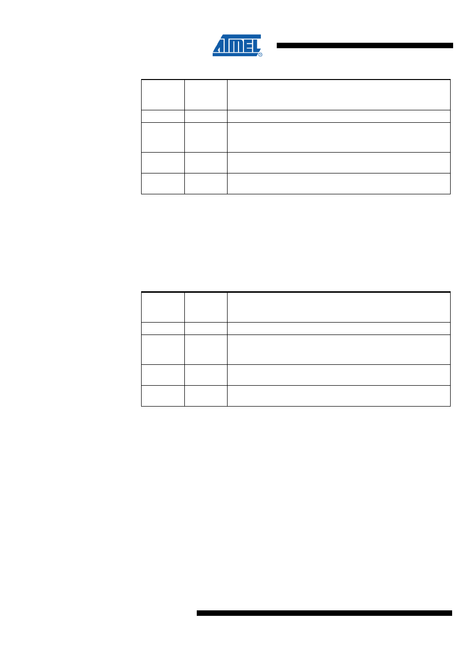
Table 18-3. Compare Output Mode, Fast PWM
COMnA1
COMnB1
COMnC1
COMnA0
COMnB0
COMnC0
Description
0
0
Normal port operation, OCnA/OCnB/OCnC disconnected.
0
1
WGM13:0 = 14 or 15: Toggle OC1A on Compare Match, OC1B and
OC1C disconnected (normal port operation). For all other WGM1
settings, normal port operation, OC1A/OC1B/OC1C disconnected.
1
0
Clear OCnA/OCnB/OCnC on compare match; set
OCnA/OCnB/OCnC at BOTTOM (non-inverting mode).
1
1
Set OCnA/OCnB/OCnC on compare match, clear
OCnA/OCnB/OCnC at BOTTOM (inverting mode).
Note:
1. A special case occurs when OCRnA/OCRnB/OCRnC equals TOP and
COMnA1/COMnB1/COMnC1 is set. In this case the compare match is ignored, but
the set or clear is done at BOTTOM. See
for more
details.
Table 18-4 shows the COMnx1:0 bit functionality when the WGMn3:0 bits are set to the
phase correct and phase and frequency correct PWM mode.
Table 18-4. Compare Output Mode, Phase Correct and Phase/Frequency Correct
PWM
COMnA1
COMnB1
COMnC1
COMnA0
COMnB0
COMnC0
Description
0
0
Normal port operation, OCnA/OCnB/OCnC disconnected.
0
1
WGM13:0 =9 or 11: Toggle OC1A on Compare Match, OC1B and
OC1C disconnected (normal port operation). For all other WGM1
settings, normal port operation, OC1A/OC1B/OC1C disconnected.
1
0
Clear OCnA/OCnB/OCnC on compare match when up-counting.
Set OCnA/OCnB/OCnC on compare match when down-counting.
1
1
Set OCnA/OCnB/OCnC on compare match when up-counting.
Clear OCnA/OCnB/OCnC on compare match when down-counting.
Note:
1. A special case occurs when OCRnA/OCRnB/OCRnC equals TOP and
COMnA1/COMnB1/COMnC1 is set. See
"Phase and Frequency Correct PWM
for more details.
18.9 Modes of Operation
The mode of operation i.e., the behavior of the Timer/Counter and the Output Compare
pins, is defined by the combination of the Waveform Generation mode (WGMn3:0) and
the Compare Output mode (COMnx1:0) bits. The Compare Output mode bits do not
affect the counting sequence, but the Waveform Generation mode bits do. The
COMnx1:0 bits control whether the PWM output generated should be inverted or not
(inverted or non-inverted PWM). For non-PWM modes the COMnx1:0 bits control if the
output should be set, cleared or toggle at a compare match (See
)