4 register description, 1 gtccr - general timer/counter control register, Atmega128rfa1 – Rainbow Electronics ATmega128RFA1 User Manual
Page 305
305
8266A-MCU Wireless-12/09
ATmega128RFA1
Enabling and disabling of the clock input must be done when Tn has been stable for at
least one system clock cycle. Otherwise there is a risk of generating a false
Timer/Counter clock pulse.
Each half period of the applied, external clock must be longer than one system clock
cycle to ensure correct sampling. The external clock must be guaranteed to have less
than half the system clock frequency (f
ExtClk
< f
clk_I/O
/2) given a 50/50% duty cycle. Since
the edge detector uses sampling, the maximum frequency of a detectable external
clock is half the sampling frequency (Nyquist sampling theorem). However due to
variation of the system clock frequency and duty cycle caused by Oscillator source
(crystal, resonator and capacitors) tolerances, it is recommended to limit the maximum
frequency of an external clock source to less than f
clk_I/O
/2.5. An external clock source
can not be prescaled.
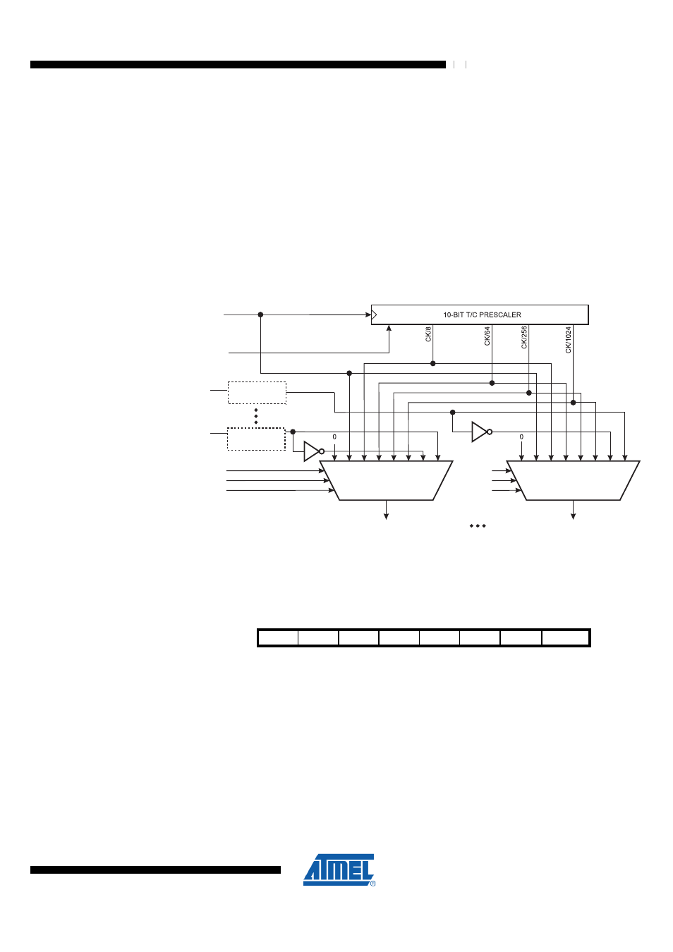
Figure 19-2. Prescaler for synchronous Timer/Counters
PSR10
Clear
Tn
Tn
clk
I/O
Synchronization
Synchronization
TIMER/COUNTERn CLOCK SOURCE
clk
Tn
TIMER/COUNTERn CLOCK SOURCE
clk
Tn
CSn0
CSn1
CSn2
CSn0
CSn1
CSn2
19.4 Register Description
19.4.1 GTCCR – General Timer/Counter Control Register
Bit
7
6
5
4
3
2
1
0
$23 ($43)
TSM
Res4
Res3
Res2
Res1
Res0
PSRASY PSRSYNC
GTCCR
Read/Write
RW
R
R
R
R
R
R
RW
Initial Value
0
0
0
0
0
0
0
0
•
Bit 7 – TSM - Timer/Counter Synchronization Mode
Writing the TSM bit to one activates the Timer/Counter Synchronization mode. In this
mode the value that is written to the PSRASY and PSRSYNC bits is kept, hence
keeping the corresponding prescaler reset signals asserted. This ensures that the
corresponding Timer/Counters are halted and can be configured to the same value
without the risk of one of them advancing during the configuration. When the TSM bit is
written to zero, the PSRASY and PSRSYNC bits are cleared by hardware and the
Timer/Counters simultaneously start counting.
•
Bit 6:2 – Res4:0 - Reserved