Table 23-2 on, Atmega128rfa1 – Rainbow Electronics ATmega128RFA1 User Manual
Page 354
354
8266A-MCU Wireless-12/09
ATmega128RFA1
The following equations can be used to calculate the ratio of the incoming data rate and
internal receiver baud rate.
MF
fast
F
slow
S
S
D
S
D
R
S
S
D
S
S
D
R
+
+
+
=
+
⋅
+
−
+
=
)
1
(
)
2
(
1
)
1
(
D
Sum of character size and parity size (D = 5 to 10 bit)
S
Samples per bit. S = 16 for normal speed mode and S = 8 for double speed
mode.
S
F
First sample number used for majority voting. S
F
= 8 for normal speed and
S
F
= 4 for double speed mode.
S
M
Middle sample number used for majority voting. S
M
= 9 for normal speed and
S
M
= 5 for double speed mode.
R
slow
is the ratio of the slowest incoming data rate that can be accepted in relation to
the receiver baud rate.
R
fast
is the ratio of the fastest incoming data rate that can be accepted in relation to
the receiver baud rate.
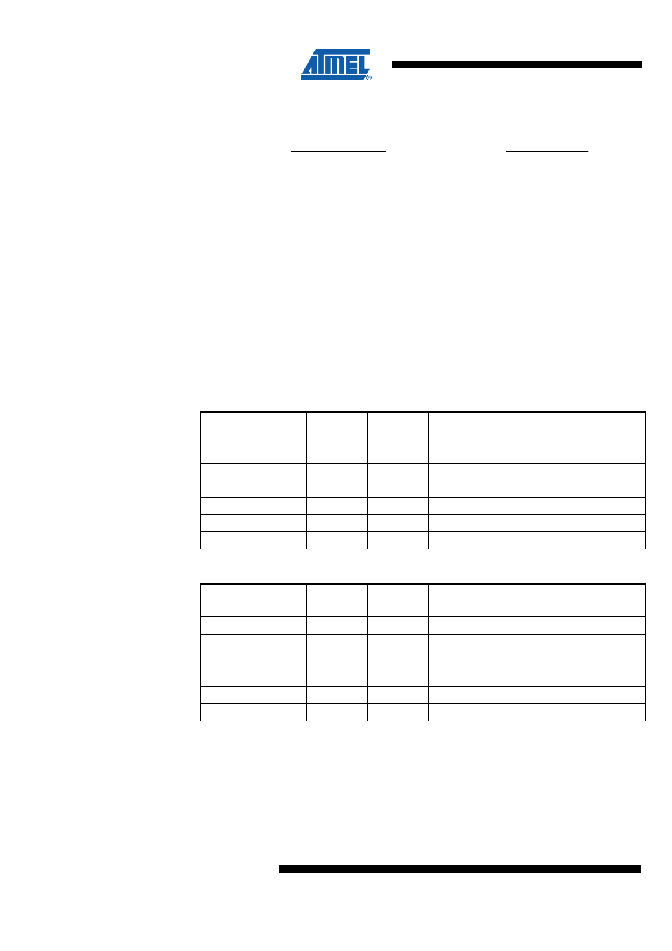
list the maximum receiver baud rate error that
can be tolerated. Note that normal speed mode has higher tolerance of baud rate
variations.
Table 23-2. Recommended Maximum Receiver Baud Rate Error for Normal Speed Mode
(U2Xn = 0)
D
# (Data+Parity Bit)
R
slow
(%)
R
fast
(%)
Max Total Error (%)
Recommended Max
Receiver Error (%)
5
93.20
106.67
+6.67/-6.8
± 3.0
6
94.12
105.79
+5.79/-5.88
± 2.5
7
94.81
105.11
+5.11/-5.19
± 2.0
8
95.36
104.58
+4.58/-4.54
± 2.0
9
95.81
104.14
+4.14/-4.19
± 1.5
10
96.17
103.78
+3.78/-3.83
± 1.5
Table 23-3. Recommended Maximum Receiver Baud Rate Error for Double Speed
Mode (U2Xn = 1)
D
# (Data+Parity Bit)
R
slow
(%)
R
fast
(%)
Max Total Error (%)
Recommended Max
Receiver Error (%)
5
94.12
105.66
+5.66/-5.88
± 2.5
6
94.92
104.92
+4.92/-5.08
± 2.0
7
95.52
104,35
+4.35/-4.48
± 1.5
8
96.00
103.90
+3.90/-4.00
± 1.5
9
96.39
103.53
+3.53/-3.61
± 1.5
10
96.70
103.23
+3.23/-3.30
± 1.0
The recommendations of the maximum receiver baud rate error were made under the
assumption that the receiver and transmitter equally divides the maximum total error.
There are two possible sources for the receiver baud rate error. The receiver’s system
clock will always have some minor instability over the supply voltage range and the
temperature range. When using the radio transceiver crystal oscillator (XOSC) to
generate the system clock, this is rarely a problem, but for the internal RC oscillator the
system clock may differ more than 2% over the temperature range. The second source
for the error is more controllable. The baud rate generator can not always do an exact