2 pll_on and rx_on states, 3 busy_tx and rx_on states, Atmega128rfa1 – Rainbow Electronics ATmega128RFA1 User Manual
Page 40
40
8266A-MCU Wireless-12/09
ATmega128RFA1
During this wake-up procedure the calibration of the filter-tuning network (FTN) is
performed. Entering TRX_OFF state is signaled by the TRX24_AWAKE interrupt, if
enabled.
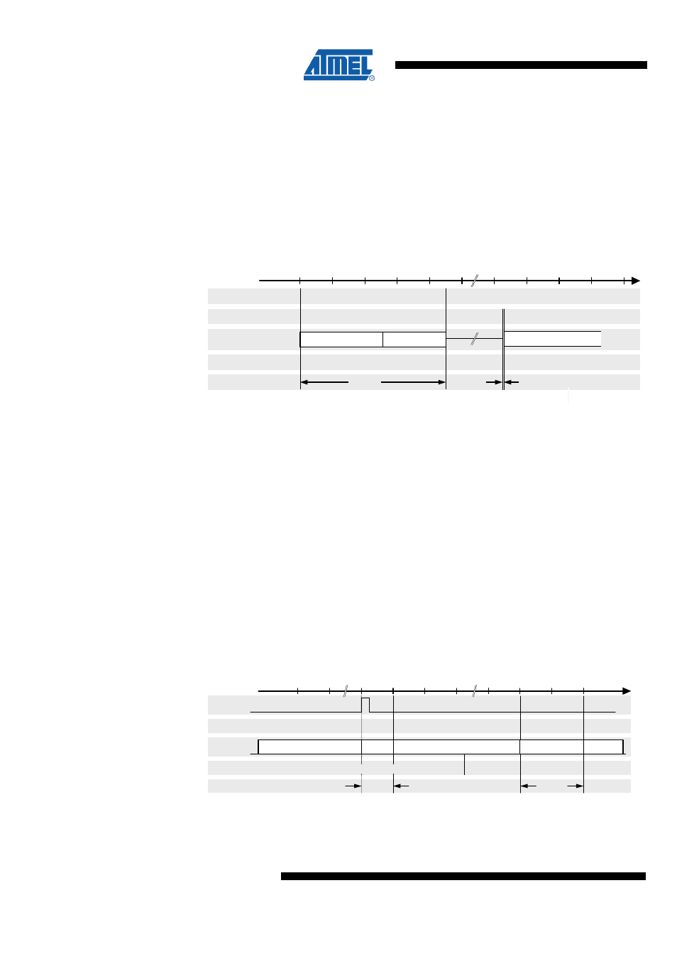
9.4.1.4.2 PLL_ON and RX_ON States
The transition from TRX_OFF to PLL_ON and RX_ON mode is shown in
.
Figure 9-15. Transition from TRX_OFF to PLL_ON and RX_ON State
0
Event
State
Block
100
Time [µs]
Time
t
TR4
TRX24_PLL_LOCK IRQ
TRX_OFF
AVREG
Command
PLL_ON
PLL
RX
PLL_ON
RX_ON
t
TR8
RX_ON
Note:
1. If TRX_CMD = RX_ON in TRX_OFF state RX_ON state is entered immediately,
even if the PLL has not settled.
2. If the AVR ADC module is enabled, the AVREG is already started and thus the
state transition time t
TR4
is reduced.
Entering the commands PLL_ON or RX_ON in TRX_OFF state initiates a ramp-up
sequence of the internal 1.8V voltage regulator for the analog domain (AVREG), if
AVREG is not already enabled by the AVR ADC module. RX_ON state can be entered
any time from PLL_ON state regardless whether the PLL has already locked as
indicated by the TRX24_PLL_LOCK interrupt.
9.4.1.4.3 BUSY_TX and RX_ON States
The transition from PLL_ON to BUSY_TX state and subsequent to RX_ON state is
shown in
.
Figure 9-16. PLL_ON to BUSY_TX to RX_ON Timing
Tim e [µ s]
0
x
16
x + 32
Tim e
t
TR 11
t
TR 10
C om m and
R X_O N
S tate
B lock
PLL_O N
RX_O N
BUSY_TX
E vent
SLPTR
PA
PLL
PA, TX
RX
PLL
or com m and TX_START
Starting from PLL_ON state it is assumed that the PLL is already locked. A
transmission is initiated either by writing “1” to bit SLPTR or by command TX_START.
The PLL settles to the transmit frequency and the PA is enabled.