46 tccr5a - timer/counter5 control register a, Atmega128rfa1 – Rainbow Electronics ATmega128RFA1 User Manual
Page 294
294
8266A-MCU Wireless-12/09
ATmega128RFA1
•
Bit 5 – ICF4 - Timer/Counter4 Input Capture Flag
The Timer/Counter4 has only limited functionality. It does not have an Input Capture
pin. Therefore this bit has no useful meaning.
•
Bit 4 – Res - Reserved Bit
This bit is reserved for future use. A read access always will return zero. A write access
does not modify the content.
•
Bit 3 – OCF4C - Timer/Counter4 Output Compare C Match Flag
This flag is set in the timer clock cycle after the counter (TCNT4) value matches the
Output Compare Register C (OCR4C). Note that a Forced Output Compare (FOC4C)
strobe will not set the OCF4C Flag. OCF4C is automatically cleared when the Output
Compare Match C Interrupt Vector is executed. Alternatively, OCF4C can be cleared by
writing a logic one to its bit location.
•
Bit 2 – OCF4B - Timer/Counter4 Output Compare B Match Flag
This flag is set in the timer clock cycle after the counter (TCNT4) value matches the
Output Compare Register B (OCR4B). Note that a Forced Output Compare (FOC4B)
strobe will not set the OCF4B Flag. OCF4B is automatically cleared when the Output
Compare Match B Interrupt Vector is executed. Alternatively, OCF4B can be cleared by
writing a logic one to its bit location.
•
Bit 1 – OCF4A - Timer/Counter4 Output Compare A Match Flag
This flag is set in the timer clock cycle after the counter (TCNT4) value matches the
Output Compare Register A (OCR4A). Note that a Forced Output Compare (FOC4A)
strobe will not set the OCF4A Flag. OCF4A is automatically cleared when the Output
Compare Match A Interrupt Vector is executed. Alternatively, OCF4A can be cleared by
writing a logic one to its bit location.
•
Bit 0 – TOV4 - Timer/Counter4 Overflow Flag
The setting of this flag is dependent of the WGM43:0 bits setting of the Timer/Counter4
Control Register. In Normal and CTC modes, the TOV4 Flag is set when the timer
overflows. TOV4 is automatically cleared when the Timer/Counter4 Overflow Interrupt
Vector is executed. Alternatively, TOV4 can be cleared by writing a logic one to its bit
location.
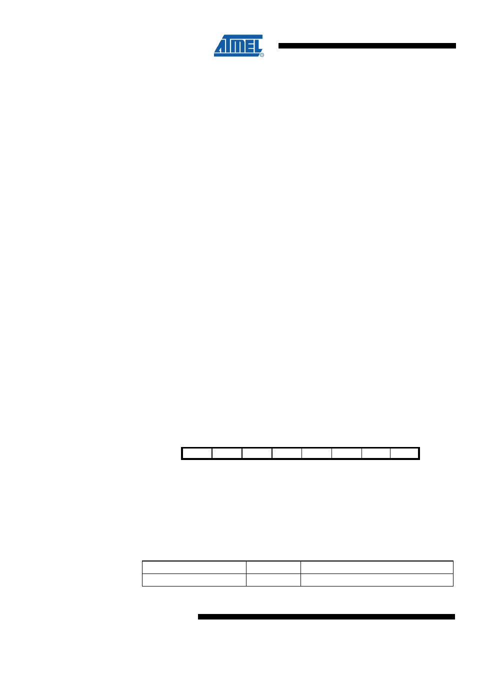
18.11.46 TCCR5A – Timer/Counter5 Control Register A
Bit
7
6
5
4
3
2
1
0
NA ($120)
COM5A1 COM5A0 COM5B1 COM5B0 COM5C1 COM5C0 WGM51 WGM50
TCCR5A
Read/Write
RW
RW
RW
RW
RW
RW
RW
RW
Initial Value
0
0
0
0
0
0
0
0
•
Bit 7:6 – COM5A1:0 - Compare Output Mode for Channel A
The Timer/Counter5 has only limited functionality. Therefore the COM5A1:0 bits do not
control the output compare behavior of any pin. The following table shows the
COM5A1:0 bit functionality when the WGM53:0 bits are set to a normal or a CTC mode
(non-PWM). For the other functionality refer to section "Modes of Operation".
Table 18-24 COM5A Register Bits
Register Bits
Value
Description
COM5A1:0
0
Normal operation