Atmega128rfa1 – Rainbow Electronics ATmega128RFA1 User Manual
Page 4
4
8266A-MCU Wireless-12/09
ATmega128RFA1
Spectrum Signal (DSSS) processing with spreading and despreading. The device is
fully compatible with IEEE802.15.4-2006/2003 and ZigBee standards.
The ATmega128RFA1 provides the following features: 128 kbytes of In-System
Programmable (ISP) Flash with read-while-write capabilities, 4 kbytes EEPROM, 16
kbytes SRAM, up to 35 general purpose I/O lines, 32 general purpose working
registers, Real Time Counter (RTC), 6 flexible Timer/Counters with compare modes
and PWM, USART, a byte oriented 2-wire Serial Interface, a 8 channel, 10 bit analog to
digital converter (ADC) with an optional differential input stage with programmable gain,
programmable Watchdog Timer with Internal Oscillator, a SPI serial port, IEEE std.
1149.1 compliant JTAG test interface, also used for accessing the On-chip Debug
system and programming and 6 software selectable power saving modes.
The Idle mode stops the CPU while allowing the SRAM, Timer/Counters, SPI port, and
interrupt system to continue functioning. The Power-down mode saves the register
contents but freezes the Oscillator, disabling all other chip functions until the next
interrupt or hardware reset. In Power-save mode, the asynchronous timer continues to
run, allowing the user to maintain a timer base while the rest of the device is sleeping.
The ADC Noise Reduction mode stops the CPU and all I/O modules except
asynchronous timer and ADC, to minimize switching noise during ADC conversions. In
Standby mode, the RC oscillator is running while the rest of the device is sleeping. This
allows very fast start-up combined with low power consumption. In Extended Standby
mode, both the main RC oscillator and the asynchronous timer continue to run.
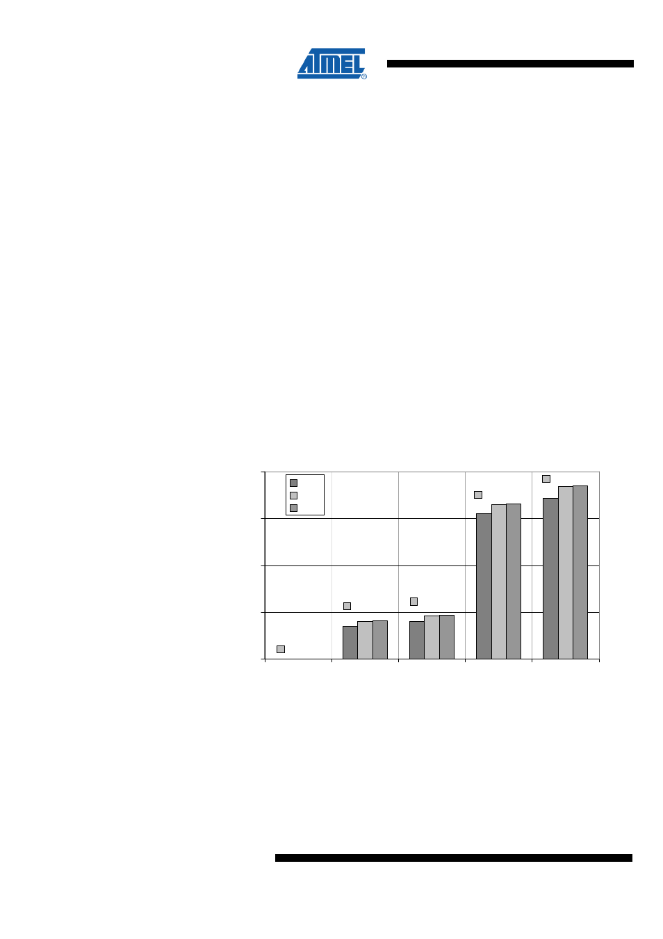
Typical supply current of the microcontroller with CPU clock set to 16MHz and the radio
transceiver for the most important states is shown in the
.
Figure 3-2 Radio transceiver and microcontroller (16MHz) supply current
16,6mA
4,7mA
4,1mA
250nA
18,6mA
0
5
10
15
20
Deep Sleep
SLEEP
TRX_OFF
RX_LISTEN
TX_ACT
Radio Transceiver State
I(
D
E
V
D
D
,E
V
D
D
)
[m
A
]
1.8V
3.0V
3.6V
The transmit output power is set to maximum. If the radio transceiver is in SLEEP mode
the current is dissipated by the AVR microcontroller only.
In Deep Sleep mode all major digital blocks with no data retention requirements are
disconnected from main supply providing a very small leakage current. Watchdog timer,
MAC symbol counter and 32.768kHz oscillator can be configured to continue to run.
The device is manufactured using Atmel’s high-density nonvolatile memory technology.
The On-chip ISP Flash allows the program memory to be reprogrammed in-system