11 ubrr1h - usart1 baud rate register high byte, Atmega128rfa1 – Rainbow Electronics ATmega128RFA1 User Manual
Page 364
364
8266A-MCU Wireless-12/09
ATmega128RFA1
Table 23-11 USBS1 Register Bits
Register Bits
Value
Description
0x00
1-bit
USBS1
0x01
2-bit
•
Bit 2:1 – UCSZ11:10 - Character Size
The UCSZ11:0 bits combined with the UCSZ12 bit in UCSR1B sets the number of data
bits (Character Size) in the frame that the Receiver and Transmitter use.
Table 23-12 UCSZ1 Register Bits
Register Bits
Value
Description
0
5-bit
1
6-bit
2
7-bit
3
8-bit
4
Reserved
5
Reserved
6
Reserved
UCSZ11:10
7
9-bit
•
Bit 0 – UCPOL1 - Clock Polarity
This bit is used for synchronous mode only. Write this bit to zero when asynchronous
mode is used. The UCPOL1 bit sets the relationship between data output change and
data input sample, and the synchronous clock (XCK1).
Table 23-13 UCPOL1 Register Bits
Register Bits
Value
Description
0
Rising XCKn Edge (Transmitted Data
Changed), Falling XCKn Edge (Received
Data Sampled)
UCPOL1
1
Falling XCKn Edge (Transmitted Data
Changed), Rising XCKn Edge (Received
Data Sampled)
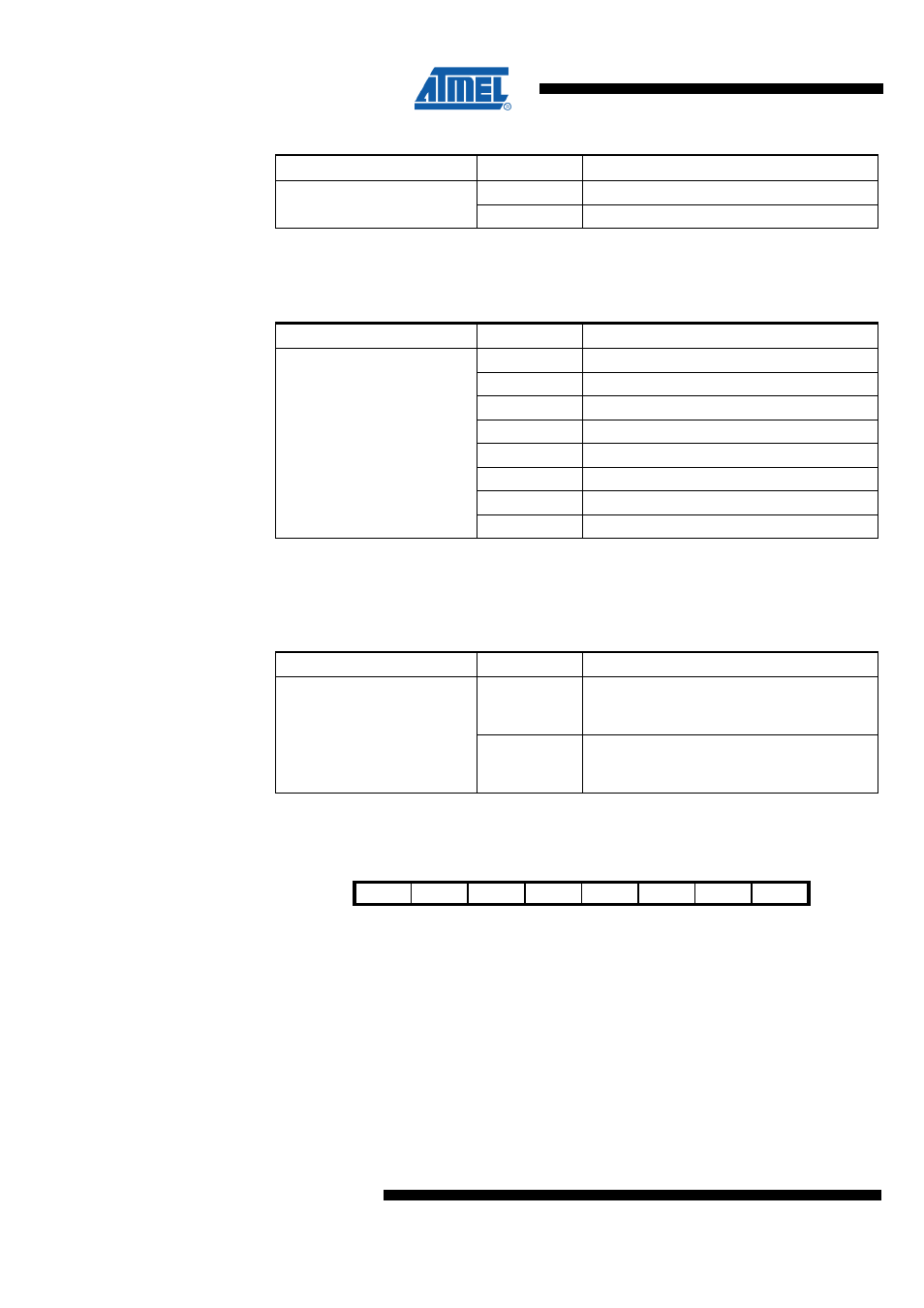
23.10.11 UBRR1H – USART1 Baud Rate Register High Byte
Bit
7
6
5
4
3
2
1
0
NA ($CD)
Res3
Res2
Res1
Res0
UBRR11 UBRR10 UBRR9
UBRR8
UBRR1H
Read/Write
R
R
R
R
RW
RW
RW
RW
Initial Value
0
0
0
0
0
0
0
0
UBRR1 is a 12-bit register which contains the USART baud rate. The UBRR1H
contains the four most significant bits, and the UBRR1L contains the eight least
significant bits of the USART baud rate. Ongoing transmissions by the Transmitter and
Receiver will be corrupted if the baud rate is changed. Writing UBRR1L will trigger an
immediate update of the baud rate prescaler.
•
Bit 7:4 – Res3:0 - Reserved Bit
This bit is reserved for future use. A read access always will return zero. A write access
does not modify the content.