6 frequency synthesizer (pll), 1 overview, 2 rf channel selection – Rainbow Electronics ATmega128RFA1 User Manual
Page 82: 3 frequency agility, Figure, Atmega128rfa1
82
8266A-MCU Wireless-12/09
ATmega128RFA1
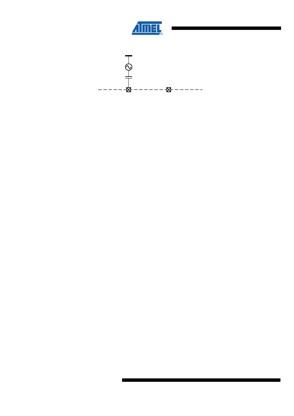
Figure 9-26. Setup for Using an External Frequency Reference
XTAL2
XTAL1
IC internal
PCB
16 MHz
9.6.6 Frequency Synthesizer (PLL)
The main features of the phase-locked loop are:
•
Generate RX/TX frequencies for all 2.4 GHz channels of IEEE 802.15.4;
•
Autonomous calibration loops for stable operation within the operating range;
•
Two PLL-interrupts for status indication;
•
Fast PLL settling to support frequency hopping;
9.6.6.1 Overview
The PLL generates the RF frequencies for the radio transceiver. During receive
operation the frequency synthesizer works as a local oscillator for the receive frequency
of the radio transceiver. During transmit operation the voltage-controlled oscillator
(VCO) is directly modulated to generate the RF transmit signal. The frequency
synthesizer is implemented as a fractional-N PLL.
Two calibration loops ensure correct PLL functionality within the specified operating
limits.
9.6.6.2 RF Channel Selection
The PLL is designed to support 16 channels in the 2.4 GHz ISM band with channel
spacing of 5 MHz according to IEEE 802.15.4. The center frequency of these channels
is defined as follows:
F
c
= 2405 + 5 (k – 11) in [MHz], for k = 11, 12 ... 26
where k is the channel number.
The channel k is selected by the CHANNEL bits of register PHY_CC_CA.
9.6.6.3 Frequency Agility
When the PLL is enabled during state transition from TRX_OFF to PLL_ON the settling
time is typically t
TR4
= 110 µs including the settling time of the analog voltage regulator
(AVREG) and the PLL self calibration (refer to
Table 9-8
and
? ?
? ? ? ? ? ? ? ? ?
).
A lock of the PLL is indicated with a TRX24_PLL_LOCK interrupt.
Switching between 2.4 GHz ISM band channels in PLL_ON or RX_ON states is
typically done within t
TR20
= 11 µs. This makes the radio transceiver highly suitable for
frequency hopping applications.
The PLL frequency is changed to the transmit frequency within t
TR23
= 16 µs after
starting the transmit procedure and before starting the transmission. After the
transmission the PLL settles back to the receive frequency within t
TR24
= 32 µs. This
frequency step does not generate a TRX24_PLL_LOCK or TRX24_PLL_UNLOCK
interrupt within these time spans.