3 dpds1 - port driver strength register 1, 4 portb - port b data register, Atmega128rfa1 – Rainbow Electronics ATmega128RFA1 User Manual
Page 205
205
8266A-MCU Wireless-12/09
ATmega128RFA1
Table 14-20 PDDRV Register Bits
Register Bits
Value
Description
0
2 mA
1
4 mA
2
6 mA
PDDRV1:0
3
8 mA
•
Bit 1:0 – PBDRV1:0 - Driver Strength Port B
Table 14-21 PBDRV Register Bits
Register Bits
Value
Description
0
2 mA
1
4 mA
2
6 mA
PBDRV1:0
3
8 mA
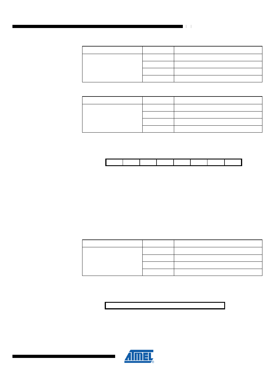
14.4.3 DPDS1 – Port Driver Strength Register 1
Bit
7
6
5
4
3
2
1
0
NA ($137)
Res5
Res4
Res3
Res2
Res1
Res0
PGDRV1 PGDRV0
DPDS1
Read/Write
R
R
R
R
R
R
RW
RW
Initial Value
0
0
0
0
0
0
0
0
The output driver strength can be set individually for each digital I/O port. The following
table shows output current levels for a typical supply voltage of DEVDD = 3.3V. Refer to
section "Electrical Characteristics" for details.
•
Bit 7:2 – Res5:0 - Reserved
•
Bit 1:0 – PGDRV1:0 - Driver Strength Port G
Driver strength can be set for port G except the port pins PG3 and PG4. The leakage
current of the ports PG3 and PG4 is reduced.
Table 14-22 PGDRV Register Bits
Register Bits
Value
Description
0
2 mA
1
4 mA
2
6 mA
PGDRV1:0
3
8 mA
14.4.4 PORTB – Port B Data Register
Bit
7
6
5
4
3
2
1
0
$05 ($25)
PORTB7:0
PORTB
Read/Write
RW
RW
RW
RW
RW
RW
RW
RW
Initial Value
0
0
0
0
0
0
0
0
If PORTBn is written logic one when the PORTB pin n is configured as an input pin, the
pull-up resistor is activated. To switch the pull-up resistor off, PORTBn has to be written