7 instruction execution timing, 8 reset and interrupt handling, Atmega128rfa1 – Rainbow Electronics ATmega128RFA1 User Manual
Page 15
15
8266A-MCU Wireless-12/09
ATmega128RFA1
7.7 Instruction Execution Timing
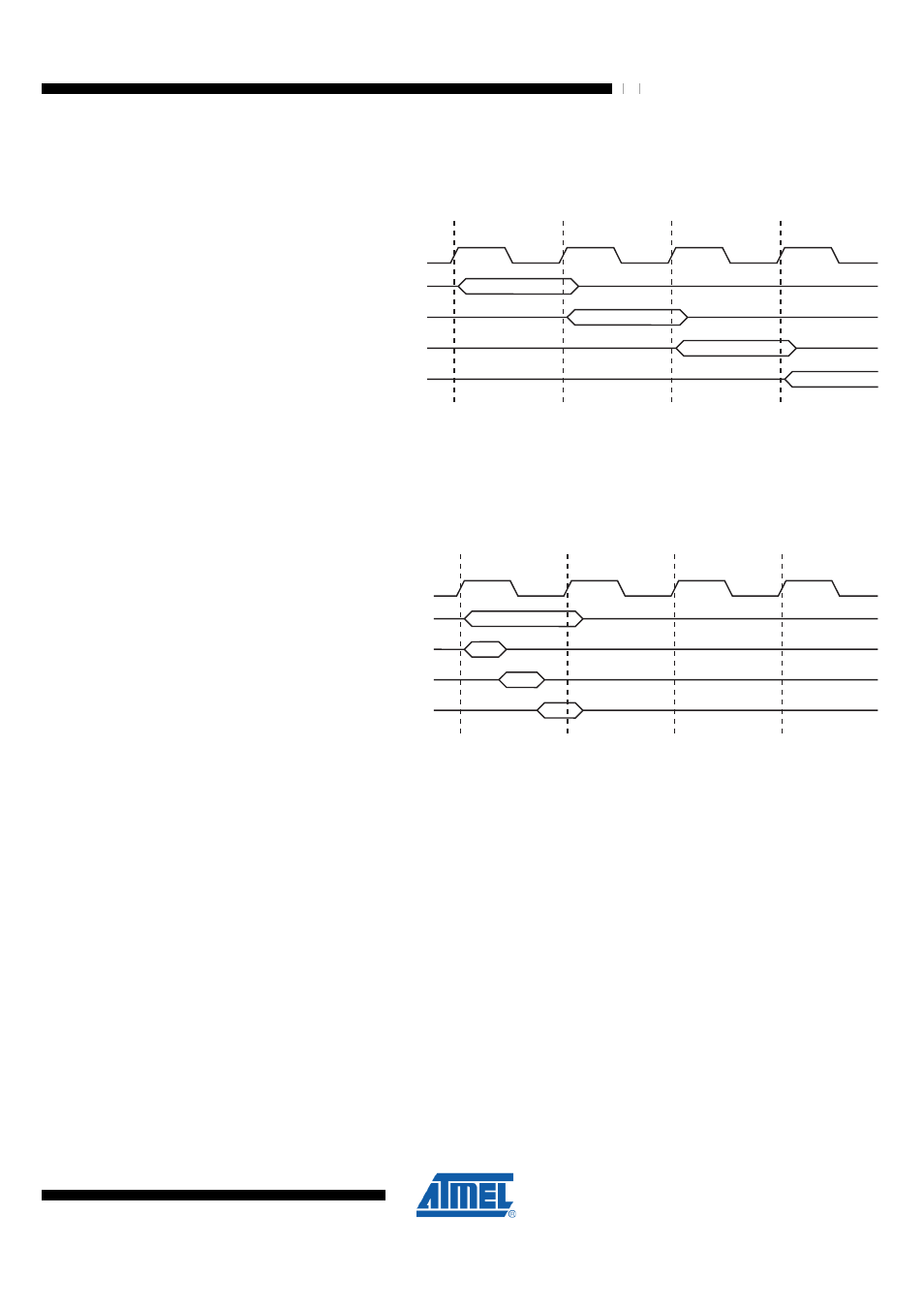
Figure 7-4. The Parallel Instruction Fetches and Instruction Executions
clk
1st Instruction Fetch
1st Instruction Execute
2nd Instruction Fetch
2nd Instruction Execute
3rd Instruction Fetch
3rd Instruction Execute
4th Instruction Fetch
T1
T2
T3
T4
CPU
shows the internal timing concept for the Register File. In a single
clock cycle an ALU operation using two register operands is executed, and the result is
stored back to the destination register.
Figure 7-5. Single Cycle ALU operation
Total Execution Time
Register Operands Fetch
ALU Operation Execute
Result Write Back
T1
T2
T3
T4
clk
CPU
7.8 Reset and Interrupt Handling
The AVR provides several different interrupt sources. These interrupts and the separate
Reset Vector each have a separate program vector in the program memory space. All
interrupts are assigned individual enable bits which must be written logic one together
with the Global Interrupt Enable bit in the Status Register in order to enable the
interrupt. Depending on the Program Counter value, interrupts may be automatically
disabled when Boot Lock bits BLB02 or BLB12 are programmed. This feature improves
software security. See the section
"Memory Programming" on page 464
The lowest addresses in the program memory space are by default defined as the
Reset and Interrupt Vectors. The complete list of vectors is shown in
. The list also determines the priority levels of the different interrupts. The
lower the address the higher is the priority level. RESET has the highest priority, and
next is INT0 – the External Interrupt Request 0. The Interrupt Vectors can be moved to
the start of the Boot Flash section by setting the IVSEL bit in the MCU Control Register
(MCUCR). Refer to
for more information. The Reset Vector
can also be moved to the start of the Boot Flash section by programming the
BOOTRST Fuse, see
"Memory Programming" on page 464
.
When an interrupt occurs, the Global Interrupt Enable I-bit is cleared and all interrupts
are disabled. The user software can write logic one to the I-bit to enable nested