5 ubrr0h - usart0 baud rate register high byte, 6 ubrr0l - usart0 baud rate register low byte, 7 udr1 - usart1 i/o data register – Rainbow Electronics ATmega128RFA1 User Manual
Page 360: Atmega128rfa1
360
8266A-MCU Wireless-12/09
ATmega128RFA1
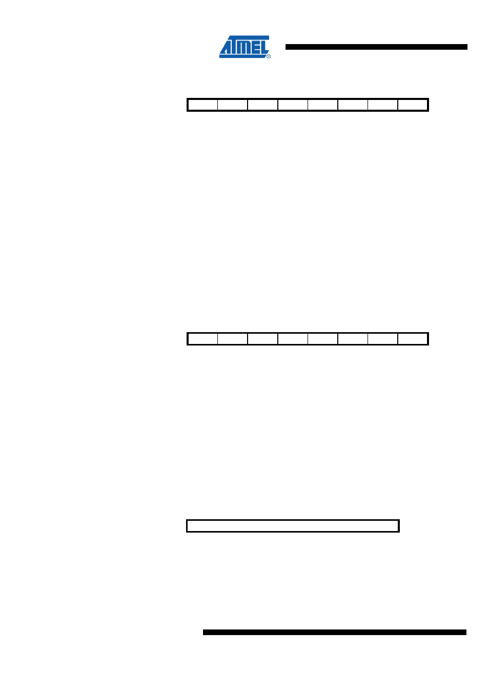
23.10.5 UBRR0H – USART0 Baud Rate Register High Byte
Bit
7
6
5
4
3
2
1
0
NA ($C5)
Res3
Res2
Res1
Res0
UBRR11 UBRR10 UBRR9
UBRR8
UBRR0H
Read/Write
R
R
R
R
RW
RW
RW
RW
Initial Value
0
0
0
0
0
0
0
0
UBRR0 is a 12-bit register which contains the USART baud rate. The UBRR0H
contains the four most significant bits, and the UBRR0L contains the eight least
significant bits of the USART baud rate. Ongoing transmissions by the Transmitter and
Receiver will be corrupted if the baud rate is changed. Writing UBRR0L will trigger an
immediate update of the baud rate prescaler.
•
Bit 7:4 – Res3:0 - Reserved Bit
This bit is reserved for future use. A read access always will return zero. A write access
does not modify the content.
•
Bit 3:0 – UBRR11:8 - USART Baud Rate Register
These bits represent bits [11:8] of the Baud Rate Register. Sample values for
commonly used clock frequencies can be found in section "Examples of Baud Rate
Setting".
23.10.6 UBRR0L – USART0 Baud Rate Register Low Byte
Bit
7
6
5
4
3
2
1
0
NA ($C4)
UBRR7
UBRR6
UBRR5
UBRR4
UBRR3
UBRR2
UBRR1
UBRR0
UBRR0L
Read/Write
RW
RW
RW
RW
RW
RW
RW
RW
Initial Value
0
0
0
0
0
0
0
0
UBRR0 is a 12-bit register which contains the USART baud rate. The UBRR0H
contains the four most significant bits, and the UBRR0L contains the eight least
significant bits of the USART baud rate. Ongoing transmissions by the Transmitter and
Receiver will be corrupted if the baud rate is changed. Writing UBRR0L will trigger an
immediate update of the baud rate prescaler.
•
Bit 7:0 – UBRR7:0 - USART Baud Rate Register
These bits represent bits [7:0] of the Baud Rate Register. Sample values for commonly
used clock frequencies can be found in section "Examples of Baud Rate Setting".
23.10.7 UDR1 – USART1 I/O Data Register
Bit
7
6
5
4
3
2
1
0
NA ($CE)
UDR17:10
UDR1
Read/Write
RW
RW
RW
RW
RW
RW
RW
RW
Initial Value
0
0
0
0
0
0
0
0
The USART Transmit Data Buffer Register and USART Receive Data Buffer Registers
share the same I/O address referred to as USART Data Register or UDR1. The
Transmit Data Buffer Register (TXB) will be the destination for data written to the UDR1
Register location. Reading the UDR1 Register location will return the contents of the