Atmega128rfa1 – Rainbow Electronics ATmega128RFA1 User Manual
Page 107
107
8266A-MCU Wireless-12/09
ATmega128RFA1
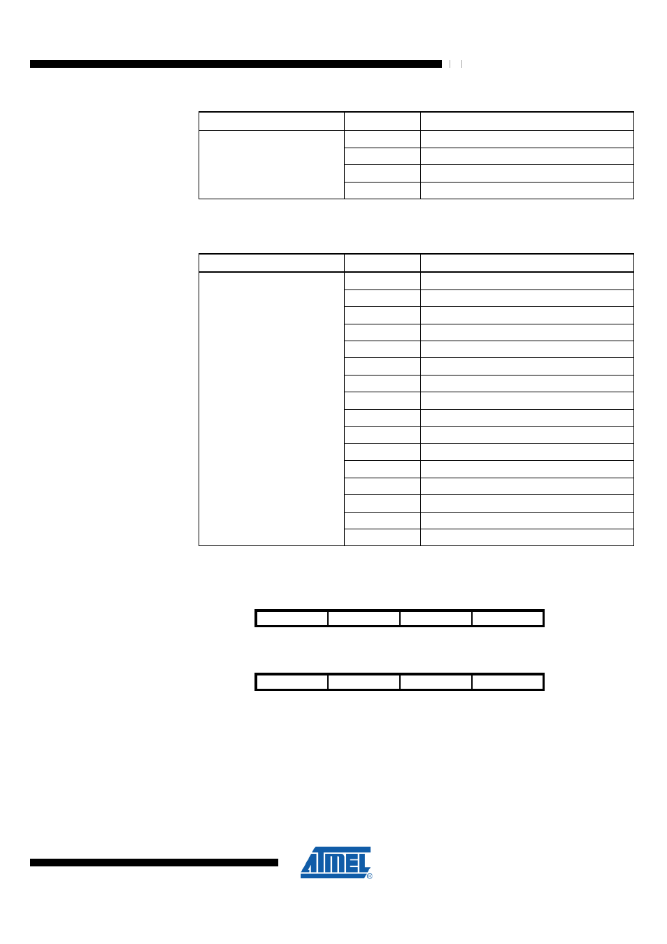
Table 9-37 PA_LT Register Bits
Register Bits
Value
Description
0
2 µs
1
4 µs
2
6 µs
PA_LT1:0
3
8 µs
•
Bit 3:0 – TX_PWR3:0 - Transmit Power Setting
These register bits determine the TX output power of the radio transceiver.
Table 9-38 TX_PWR Register Bits
Register Bits
Value
Description
0
3.0 dBm
1
2.8 dBm
2
2.3 dBm
3
1.8 dBm
4
1.3 dBm
5
0.7 dBm
6
0.0 dBm
7
-1 dBm
8
-2 dBm
9
-3 dBm
10
-4 dBm
11
-5 dBm
12
-7 dBm
13
-9 dBm
14
-12 dBm
TX_PWR3:0
15
-17 dBm
9.12.10 PHY_RSSI – Receiver Signal Strength Indicator Register
Bit
7
6
5
4
NA ($146)
RX_CRC_VALID
RND_VALUE1
RND_VALUE0
RSSI4
PHY_RSSI
Read/Write
R
R
R
R
Initial Value
0
0
0
0
Bit
3
2
1
0
NA ($146)
RSSI3
RSSI2
RSSI1
RSSI0
PHY_RSSI
Read/Write
R
R
R
R
Initial Value
0
0
0
0
The PHY_RSSI register is a multi purpose register that indicates FCS validity, provides
random numbers and shows the current RSSI value.
•
Bit 7 – RX_CRC_VALID - Received Frame CRC Status
Reading this register bit indicates whether the last received frame has a valid FCS or
not. The register bit is updated when issuing a TRX24_RX_END interrupt and remains