Atmega128rfa1 – Rainbow Electronics ATmega128RFA1 User Manual
Page 110
110
8266A-MCU Wireless-12/09
ATmega128RFA1
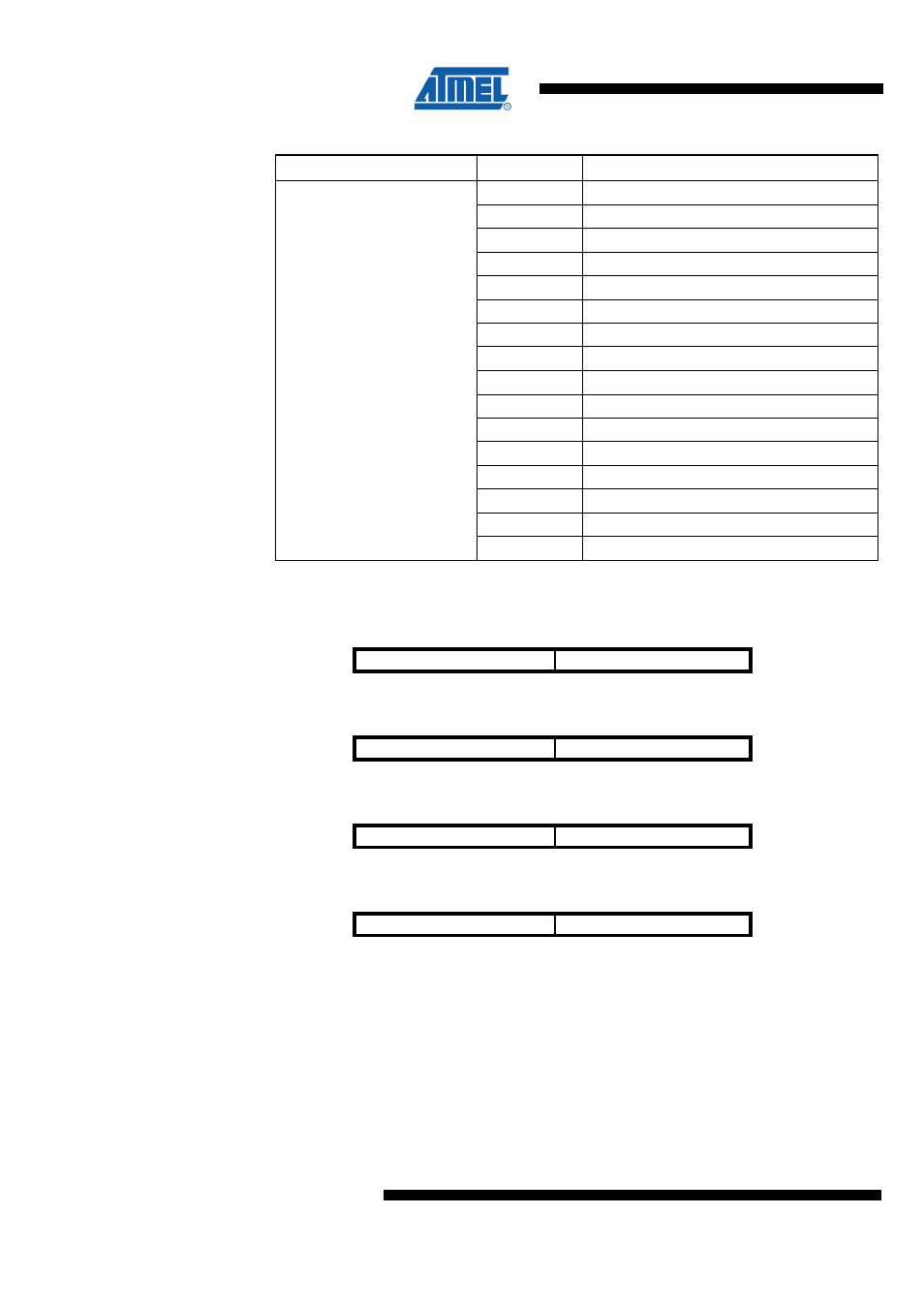
Table 9-43 CHANNEL Register Bits
Register Bits
Value
Description
11
2405 MHz
12
2410 MHz
13
2415 MHz
14
2420 MHz
15
2425 MHz
16
2430 MHz
17
2435 MHz
18
2440 MHz
19
2445 MHz
20
2450 MHz
21
2455 MHz
22
2460 MHz
23
2465 MHz
24
2470 MHz
25
2475 MHz
CHANNEL4:0
26
2480 MHz
9.12.13 CCA_THRES – Transceiver CCA Threshold Setting Register
Bit
7
6
NA ($149)
CCA_CS_THRES3
CCA_CS_THRES2
CCA_THRES
Read/Write
RW
RW
Initial Value
1
1
Bit
5
4
NA ($149)
CCA_CS_THRES1
CCA_CS_THRES0
CCA_THRES
Read/Write
RW
RW
Initial Value
0
0
Bit
3
2
NA ($149)
CCA_ED_THRES3
CCA_ED_THRES2
CCA_THRES
Read/Write
RW
RW
Initial Value
0
1
Bit
1
0
NA ($149)
CCA_ED_THRES1
CCA_ED_THRES0
CCA_THRES
Read/Write
RW
RW
Initial Value
1
1
This register sets the threshold level for the Energy Detection (ED) of the Clear Channel
Assessment (CCA).
•
Bit 7:4 – CCA_CS_THRES3:0 - CS Threshold Level for CCA Measurement
These bits are reserved for internal use.
•
Bit 3:0 – CCA_ED_THRES3:0 - ED Threshold Level for CCA Measurement