3 frame buffer, 1 data management, Atmega128rfa1 – Rainbow Electronics ATmega128RFA1 User Manual
Page 77
77
8266A-MCU Wireless-12/09
ATmega128RFA1
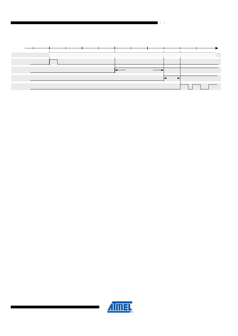
Figure 9-22. TX Power Ramping
0
6
8
10
SLPTR
TRX _STA TE
PLL_O N
2
12
14
16
18
Length [µ s]
PA buffer
4
PA
PA_BUF _LT
PA_LT
M odulation
1
1
1
1
1
1
0 0
0
BU SY_TX
When using an external RF front-end (refer to
)
it may be
required to adjust the startup time of the external PA relative to the internal building
blocks to optimize the overall PSD. This can be achieved using register bits
PA_BUF_LT and PA_LT of register PHY_TX_PWR.
9.6.3 Frame Buffer
The radio transceiver contains a 128 byte dual port SRAM. One port of the frame buffer
is directly connected to the controller I/O space. Therefore random access to single
frame bytes is possible. The other port connects to the internal transmitter and receiver
modules. Both ports are independent and simultaneously accessible for data
communication.
The Frame Buffer uses the controller I/O address space 0x180 to 0x1FF for RX and TX
operation of the radio transceiver and can keep one IEEE 802.15.4 RX or one TX frame
of maximum length at a time.
Frame Buffer access is only possible if the radio transceiver is enabled (PRTRX24 bit in
the Power Reduction Register PRR1 is not set) and not in SLEEP state.
9.6.3.1 Data Management
Data in the Frame Buffer (received data or data to be transmitted) remain valid as long
as:
•
No new frame or other data are written into the buffer;
•
No new frame is received (in any BUSY_RX state);
•
No state change into radio transceiver SLEEP state is made;
•
No radio transceiver RESET (see bit TRXRST in
) or system reset took place;
•
"PRR1 – Power Reduction Register 1" on page 168
set;
By default there is no protection of the Frame Buffer against overwriting. If a frame is
received during a Frame Buffer read access of a previously received frame, the stored
data might be overwritten.
Finally the application software should check the transferred frame data integrity by a
FCS check.
The state of the radio transceiver should be changed to PLL_ON state after reception to
protect the Frame Buffer content against overwriting with new, incoming frames. This
can be achieved by writing immediately the command PLL_ON to the TRX_CMD bits of
register TRX_STATE after receiving the frame indicated by a TRX24_RX_END
interrupt.