2 eicrb - external interrupt control register b, Atmega128rfa1 – Rainbow Electronics ATmega128RFA1 User Manual
Page 220
220
8266A-MCU Wireless-12/09
ATmega128RFA1
Table 16-128 ISC1 Register Bits
Register Bits
Value
Description
0x00
The low level of INTn generates an interrupt
request.
0x01
Any edge of INTn generates asynchronously
an interrupt request.
0x02
The falling edge of INTn generates
asynchronously an interrupt request.
ISC11:10
0x03
The rising edge of INTn generates
asynchronously an interrupt request.
•
Bit 1:0 – ISC01:00 - External Interrupt 0 Sense Control Bit
Table 16-129 ISC0 Register Bits
Register Bits
Value
Description
0x00
The low level of INTn generates an interrupt
request.
0x01
Any edge of INTn generates asynchronously
an interrupt request.
0x02
The falling edge of INTn generates
asynchronously an interrupt request.
ISC01:00
0x03
The rising edge of INTn generates
asynchronously an interrupt request.
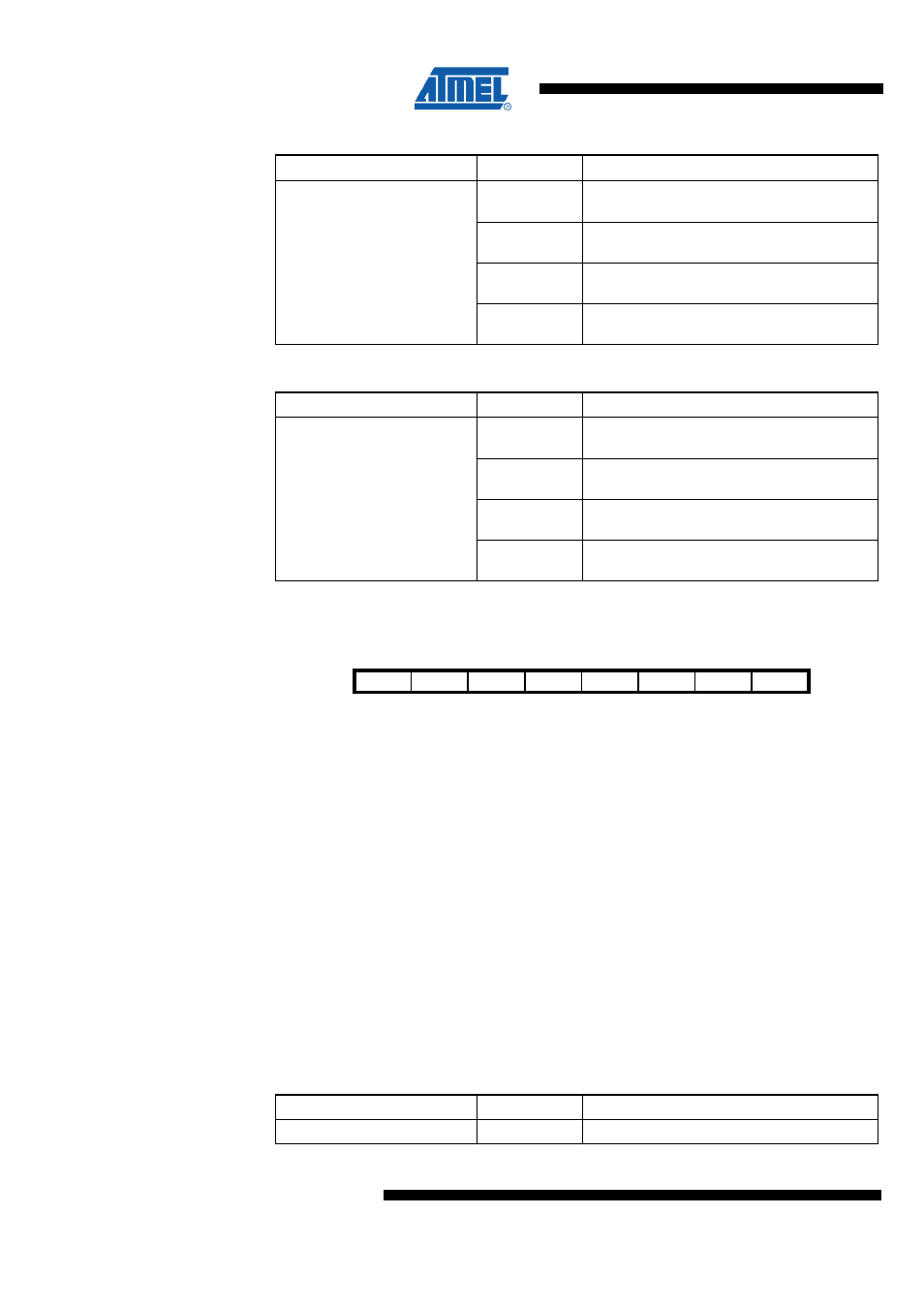
16.2.2 EICRB – External Interrupt Control Register B
Bit
7
6
5
4
3
2
1
0
NA ($6A)
ISC71
ISC70
ISC61
ISC60
ISC51
ISC50
ISC41
ISC40
EICRB
Read/Write
RW
RW
RW
RW
RW
RW
RW
RW
Initial Value
0
0
0
0
0
0
0
0
The External Interrupts 7 - 4 are activated by the external pins INT7:4 if the SREG I-flag
and the corresponding interrupt mask in the EIMSK is set. The level and edges on the
external pins that activate the interrupts are defined in the following tables. Edges on
INT7:4 are registered asynchronously. Pulses on INT7:4 pins wider than the minimum
pulse width of typical 50 ns will generate an interrupt. Shorter pulses are not
guaranteed to generate an interrupt. If low level interrupt is selected, the low level must
be held until the completion of the currently executing instruction to generate an
interrupt. If enabled, a level triggered interrupt will generate an interrupt request as long
as the pin is held low. When changing the ISCn bit, an interrupt can occur. Therefore, it
is recommended to first disable INTn by clearing its Interrupt Enable bit in the EIMSK
Register. Then, the ISCn bit can be changed. Finally, the INTn interrupt flag should be
cleared by writing a logical one to its Interrupt Flag bit (INTFn) in the EIFR Register
before the interrupt is re-enabled. When changing the ISCn1/ISCn0 bits, the interrupt
must be disabled by clearing its Interrupt Enable bit in the EIMSK Register. Otherwise
an interrupt can occur when the bits are changed.
•
Bit 7:6 – ISC71:70 - External Interrupt 7 Sense Control Bit
Table 16-130 ISC7 Register Bits
Register Bits
Value
Description
ISC71:70
0x00
The low level of INTn generates an interrupt