4 power management electrical characteristics, 1 power switches, 2 voltage regulators – Rainbow Electronics ATmega128RFA1 User Manual
Page 503: 5 2-wire serial interface characteristics, Power management electrical characteristics" on, Wire serial interface, Power management, Power management electrical, Atmega128rfa1
503
8266A-MCU Wireless-12/09
ATmega128RFA1
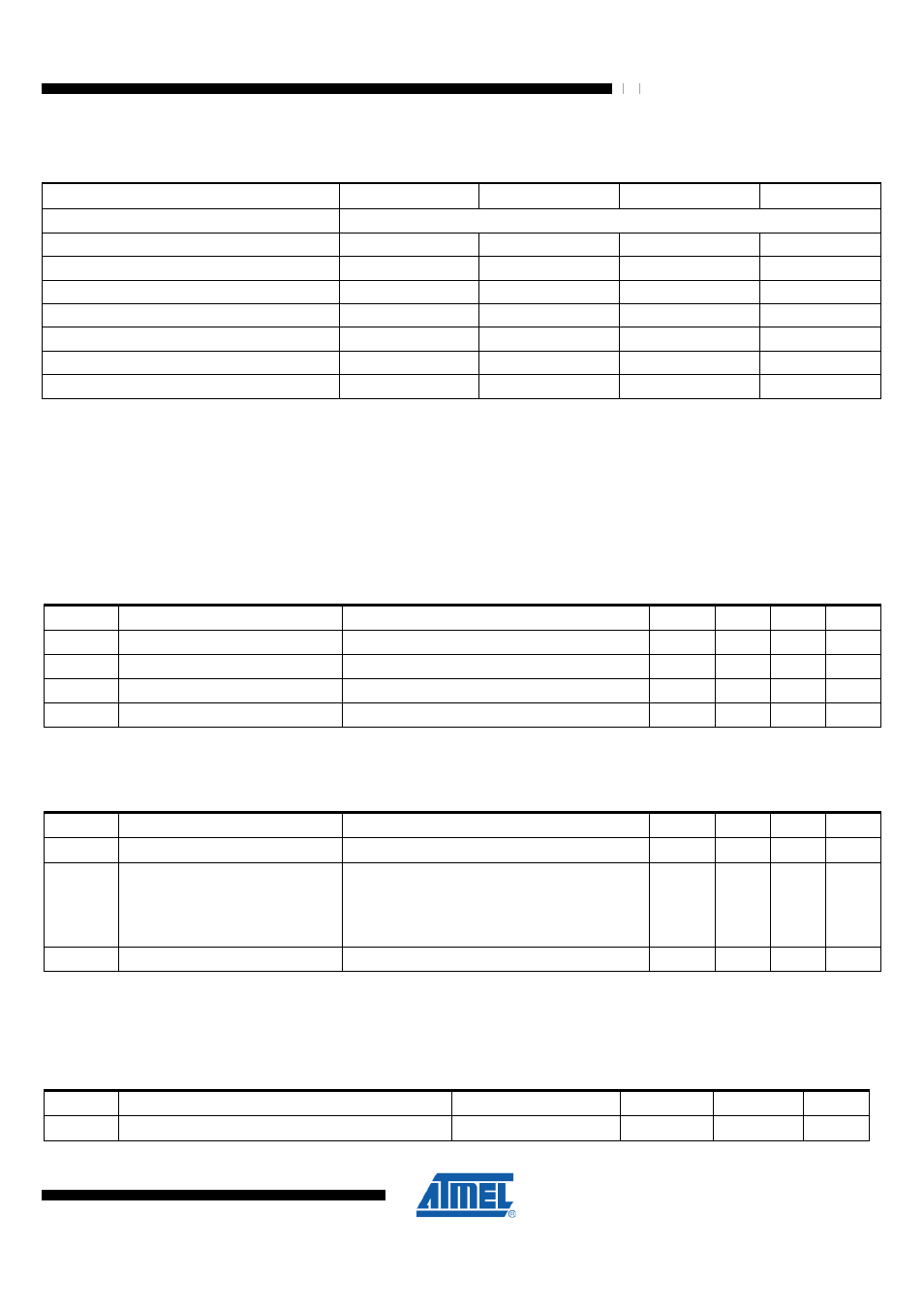
Table 34-23. BODLEVEL Fuse Coding
BODLEVEL2:0 Fuses
Min V
BOD
Typ V
BOD
Max V
BOD
Units
111
BOD Disabled
110
1.8
V
101
1.9
V
100
2.0
V
011
2.1
V
010
2.2
V
001
2.3
V
000
2.4
V
Note:
V
BOT
may be below nominal minimum operating voltage. The device is operated down to V
DEVDD
= V
BOT
during the
production test. This guarantees that a Brown-Out Reset will occur before V
DEVDD
drops to a voltage where correct
operation of the microcontroller is no longer guaranteed. The test is performed using BODLEVEL = 110 for 16 MHz
operation of the ATmega128RFA1.
34.4 Power Management Electrical Characteristics
34.4.1 Power Switches
Table 34-6. Timing Characteristics of the Power Switches
Symbol
Parameter
Condition
Min.
Typ.
Max.
Units
t
POR
Power-on reset time
Applies if the device is powered up
TBD
µs
t
BG
Bandgap startup time
7
µs
t
DRT_ON
DRT switch switch-on time
2
µs
t
PWRSW_ON
Power switch switch-on time
2
µs
34.4.2 Voltage Regulators
Table 34-7. Timing Characteristics of the Voltage regulators
Symbol
Parameter
Condition
Min.
Typ.
Max.
Units
t
AVREG
Power up time AVREG
external capacity on pin AVDD TBD
TBD
µs
t
DVREG
Power up time DVREG
Startup after wakeup,
Startup after deep sleep,
external capacity on pin DVDD TBD
TRX24 and all SRAM modules enabled)
30
µs
t
BG
Power up time bandgap
TBD
µs
34.5 2-wire Serial Interface Characteristics
The timing characteristics refer to Table 34-8.
Table 34-8 2-wire Serial Bus Requirements
Symbol
Parameter
Condition
Min.
Max.
Units
V
IL
Input Low-voltage
-0.5
0.3V
DEVDD
V