Figure 22-2 – Rainbow Electronics ATmega128RFA1 User Manual
Page 331
331
8266A-MCU Wireless-12/09
ATmega128RFA1
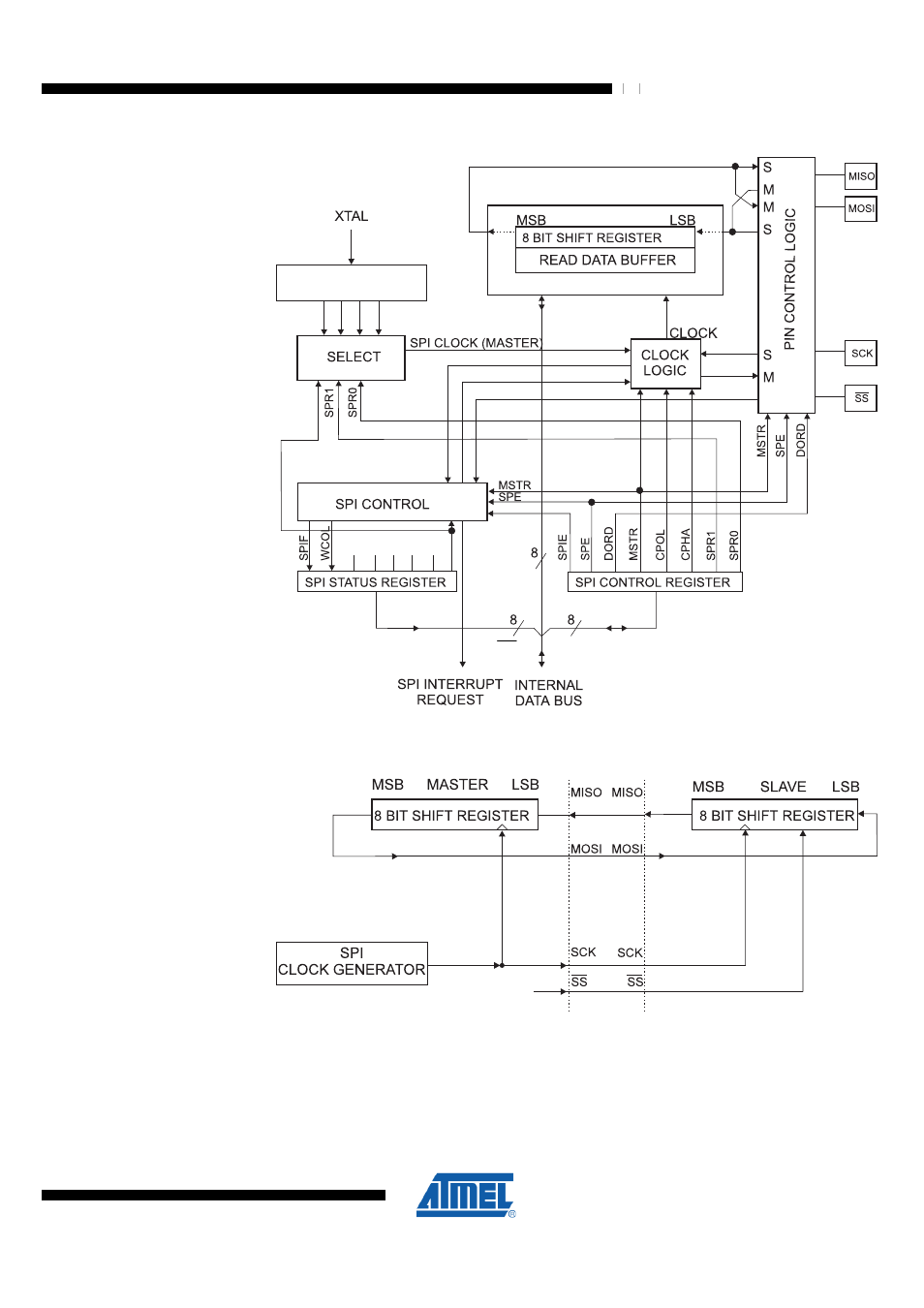
Figure 22-1. SPI Block Diagram
(1)
SPI2X
SPI2X
DIVIDER
/2/4/8/16/32/64/128
and
for SPI pin placement.
Figure 22-2. SPI Master-slave Interconnection
SHIFT
ENABLE
The system is single buffered in the transmit direction and double buffered in the
receive direction. This means that bytes to be transmitted cannot be written to the SPI
Data Register before the entire shift cycle is completed. When receiving data, however,
a received character must be read from the SPI Data Register before the next character
has been completely shifted in. Otherwise, the first byte is lost. In SPI Slave mode, the
See also other documents in the category Rainbow Electronics Sensors:
- MAX5151 (16 pages)
- MAXQ3108 (64 pages)
- MAX5661 (39 pages)
- MAX6691 (7 pages)
- MAX5362 (12 pages)
- ADC10158 (26 pages)
- MAX8922L (14 pages)
- MAX8596Z (8 pages)
- MAX7491 (18 pages)
- MAX15040 (15 pages)
- MAX5177 (16 pages)
- ADC08138 (22 pages)
- MAX5961 (42 pages)
- T89C51RD2 (86 pages)
- MAX16055 (9 pages)
- MAX6659 (17 pages)
- ADC0820 (20 pages)
- MAX6678 (19 pages)
- MAX8884Z (15 pages)
- MAX16915 (9 pages)
- MAX8620 (18 pages)
- MAX5144 (12 pages)
- MAX6670 (8 pages)
- MAX8760 (39 pages)
- W78C32C (14 pages)
- MX7533 (8 pages)
- MAX8727 (13 pages)
- MAX9053 (15 pages)
- W78C54 (16 pages)
- MAX8614B (15 pages)
- W90N740 (219 pages)
- MAX6626 (13 pages)
- ADC10738 (30 pages)
- MAX17000 (31 pages)
- MAX5051 (21 pages)
- MAXQ1004 (18 pages)
- MAX6871 (51 pages)
- MX7847 (12 pages)
- MAX6608 (6 pages)
- MAX17083 (15 pages)
- MAX6641 (17 pages)
- MAX5251 (16 pages)
- MAX6338 (8 pages)
- MAX6690 (16 pages)
- MAX8668 (18 pages)