1 latching of fuses, 3 signature bytes, Table 31-5 on – Rainbow Electronics ATmega128RFA1 User Manual
Page 466: Atmega128rfa1
466
8266A-MCU Wireless-12/09
ATmega128RFA1
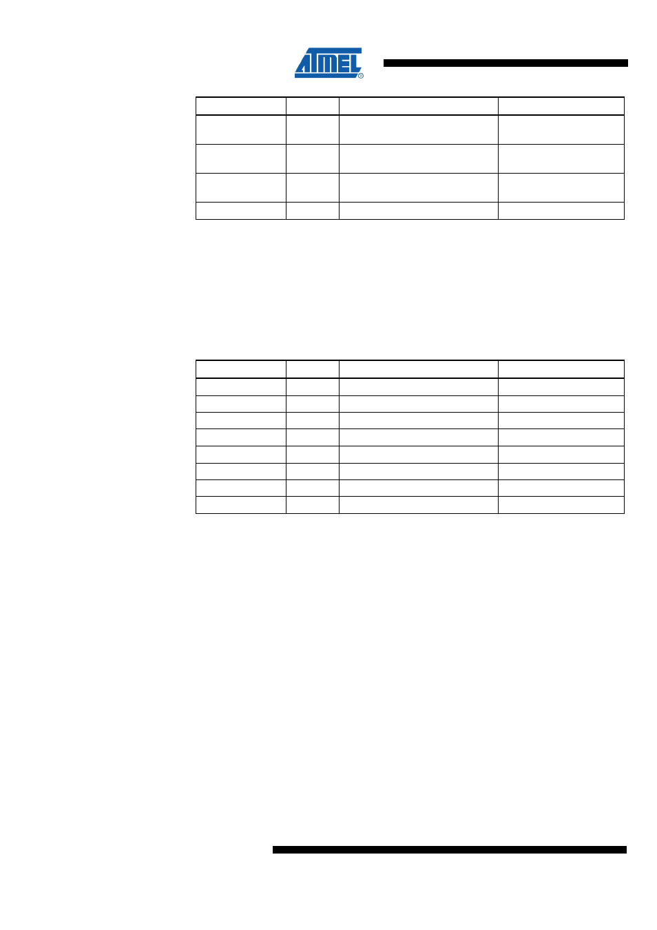
Fuse High Byte
Bit No
Description
Default Value
EESAVE
3
EEPROM memory is preserved
through the Chip Erase
1 (un-programmed,
EEPROM not preserved)
BOOTSZ1
2
BOOTSZ0
1
for details)
BOOTRST
0
Select Reset Vector
1 (un-programmed)
Notes:
1. The SPIEN Fuse is not accessible in serial programming mode.
2. The default value of BOOTSZ1:0 results in maximum Boot Size. See
3. See
"WDTCSR – Watchdog Timer Control Register" on page 183
4. Never ship a product with the OCDEN Fuse programmed regardless of the setting
of Lock bits and JTAGEN Fuse. A programmed OCDEN Fuse enables some
parts of the clock system to be running in all sleep modes. This may increase the
power consumption.
Table 31-5. Fuse Low Byte
Fuse Low Byte
Bit No
Description
Default Value
CKDIV8
(4)
7
Divide clock by 8
0 (programmed)
CKOUT
(3)
6
Clock output
1 (un-programmed)
SUT1
5
Select start-up time
1 (un-programmed)
(1)
SUT0
4
Select start-up time
0 (programmed)
(1)
CKSEL3
3
Select Clock source
0 (programmed)
(2)
CKSEL2
2
Select Clock source
0 (programmed)
(2)
CKSEL1
1
Select Clock source
1 (un-programmed)
(2)
CKSEL0
0
Select Clock source
0 (programmed)
(2)
Notes:
1. The default value of SUT1:0 results in maximum start-up time for the default clock
source. See
"System Control and Reset" on page 176
2. The default setting of CKSEL3:0 results in internal RC Oscillator @ 8 MHz. See
3. The CKOUT Fuse allows the system clock to be output on PORTE7. See
4. See
"System Clock Prescaler" on page 152
The status of the Fuse bits is not affected by Chip Erase. Note that the Fuse bits are
locked if Lock bit1 (LB1) is programmed. Program the Fuse bits before programming
the Lock bits.
31.2.1 Latching of Fuses
The fuse values are latched when the device enters programming mode and changes
of the fuse values will have no effect until the part leaves Programming mode. This
does not apply to the EESAVE Fuse which will take effect once it is programmed. The
fuses are also latched on Power-up in Normal mode.
31.3 Signature Bytes
All Atmel microcontrollers have a three-byte signature code which identifies the device.
This code can be read in both serial and parallel mode, also when the device is locked.