4 register description, 1 mcucr - mcu control register, 2 dpds0 - port driver strength register 0 – Rainbow Electronics ATmega128RFA1 User Manual
Page 204: Atmega128rfa1
204
8266A-MCU Wireless-12/09
ATmega128RFA1
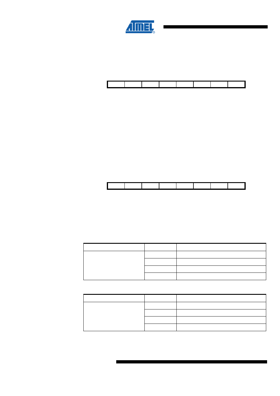
14.4 Register Description
14.4.1 MCUCR – MCU Control Register
Bit
7
6
5
4
3
2
1
0
$35 ($55)
PUD
MCUCR
Read/Write
RW
Initial Value
0
The MCU Control Register contains control bits of the general Microcontroller Unit
functions.
•
Bit 4 – PUD - Pull-up Disable
When this bit is written to one, the I/O ports pull-up resistors are disabled even if the
DDxn and PORTxn Registers are configured to enable the pull-up resistor ({DDxn,
PORTxn} = 2'b01). See section "Ports as General Digital I/O" for more details about this
feature.
14.4.2 DPDS0 – Port Driver Strength Register 0
Bit
7
6
5
4
3
2
1
0
NA ($136)
PFDRV1 PFDRV0 PEDRV1 PEDRV0 PDDRV1 PDDRV0 PBDRV1 PBDRV0
DPDS0
Read/Write
RW
RW
RW
RW
RW
RW
RW
RW
Initial Value
0
0
0
0
0
0
0
0
The output driver strength can be set individually for each digital I/O port. The following
tables show output current levels for a typical supply voltage of DEVDD = 3.3V. Refer to
section "Electrical Characteristics" for details.
•
Bit 7:6 – PFDRV1:0 - Driver Strength Port F
Table 14-18 PFDRV Register Bits
Register Bits
Value
Description
0
2 mA
1
4 mA
2
6 mA
PFDRV1:0
3
8 mA
•
Bit 5:4 – PEDRV1:0 - Driver Strength Port E
Table 14-19 PEDRV Register Bits
Register Bits
Value
Description
0
2 mA
1
4 mA
2
6 mA
PEDRV1:0
3
8 mA
•
Bit 3:2 – PDDRV1:0 - Driver Strength Port D