Atmega128rfa1 – Rainbow Electronics ATmega128RFA1 User Manual
Page 184
184
8266A-MCU Wireless-12/09
ATmega128RFA1
•
Bit 6 – WDIE - Watchdog Timeout Interrupt Enable
When this bit is written to one and the I-bit in the Status Register is set, the Watchdog
Interrupt is enabled. If WDE is cleared in combination with this setting, the Watchdog
Timer is in Interrupt Mode, and the corresponding interrupt is executed if time-out in the
Watchdog Timer occurs. If WDE is set, the Watchdog Timer is in Interrupt and System
Reset Mode. The first time-out in the Watchdog Timer will set WDIF. Executing the
corresponding interrupt vector will clear WDIE and WDIF automatically by hardware
(the Watchdog goes to System Reset Mode). This is useful for keeping the Watchdog
Timer security while using the interrupt. To stay in Interrupt and System Reset Mode,
WDIE must be set after each interrupt. This should however not be done within the
interrupt service routine itself, as this might compromise the safety-function of the
Watchdog System Reset mode. If the interrupt is not executed before the next time-out,
a System Reset will be applied.
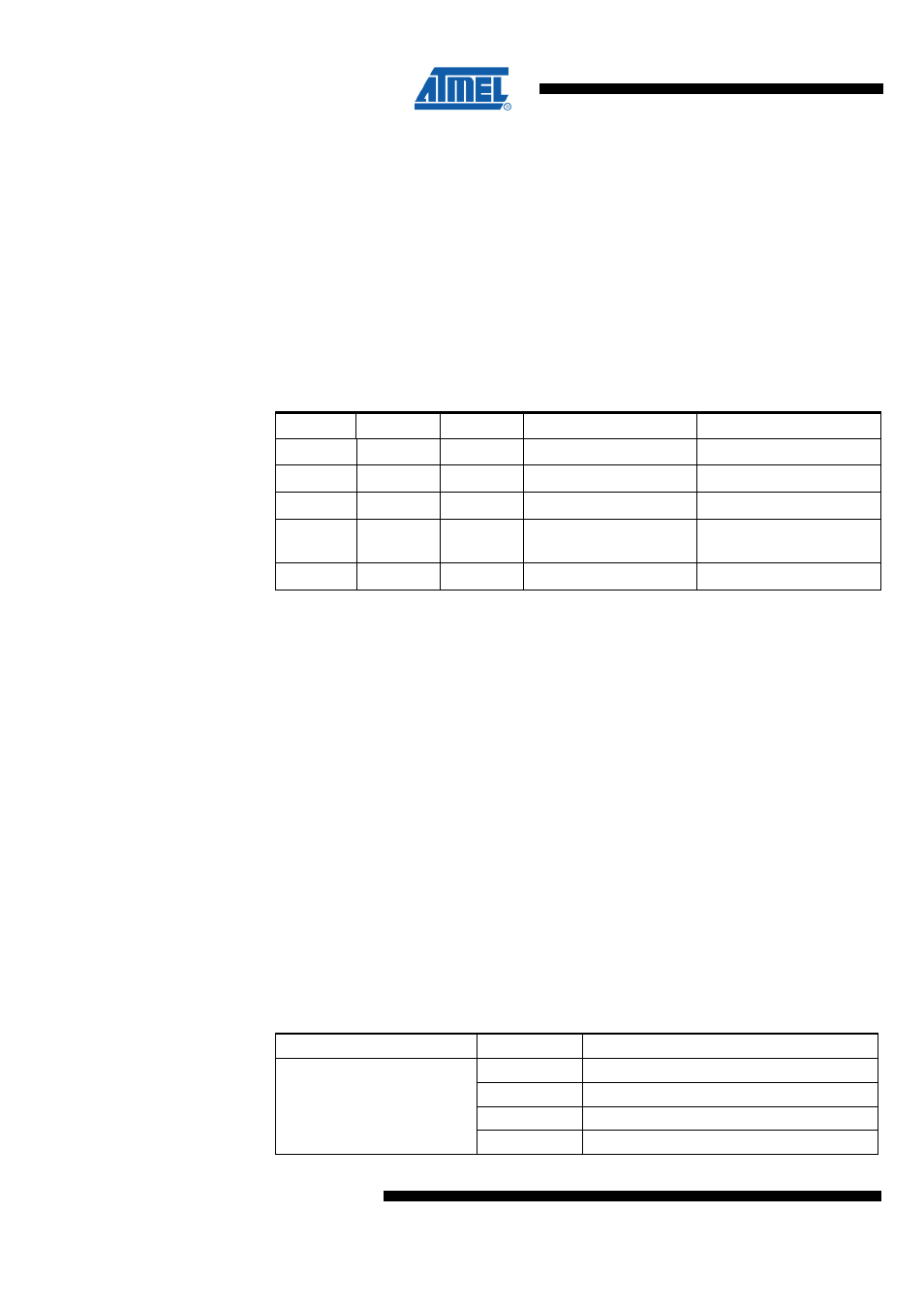
Table 13-1. Watchdog Timer Configuration
WDTON
(1)
WDE
WDIE
Mode
Action on Time-out
1
0
0
Stopped
None
1
0
1
Interrupt Mode
Interrupt
1
1
0
System Reset Mode
Reset
1
1
1
Interrupt and System
Reset Mode
Interrupt, then go to
System Reset Mode
0
x
x
System Reset Mode
Reset
Note:
1. WDTON Fuse set to “0“ means programmed and “1” means un-programmed.
•
Bit 4 – WDCE - Watchdog Change Enable
This bit is used in timed sequences for changing WDE and prescaler bits. To clear the
WDE bit, and/or change the prescaler bits, WDCE must be set. Once written to one,
hardware will clear WDCE after four clock cycles.
•
Bit 3 – WDE - Watch Dog Enable
When the WDE is set (one) the Watchdog Timer is enabled, and if the WDE is cleared
(zero) the Watchdog Timer function is disabled. WDE can only be cleared if the
WDTOE bit is set (one). To disable an enabled watchdog timer, the following procedure
must be followed: 1. In the same operation, write a logical one to WDTOE and WDE. A
logical one must be written to WDE even though it is set to one before the disable
operation starts. 2. Within the next four clock cycles, write a logical 0 to WDE. This
disables the watchdog. WDE is overridden by WDRF in MCUSR. This means that WDE
is always set when WDRF is set. To clear WDE, WDRF must be cleared first. This
feature ensures multiple resets during conditions causing failure, and a safe start-up
after the failure.
•
Bit 5, 2:0 – WDP3:0 – Watchdog Timer Prescaler 3, 2, 1 and 0
The WDP3:0 bits determine the Watchdog Timer prescaling when the Watchdog Timer
is running.
Table 13-2. WDP Register Bits
Register Bits
Value
Description
0x00
Oscillator Cycles 2k, (16ms)
0x01
Oscillator Cycles 4k, (32ms)
0x02
Oscillator Cycles 8k, (64ms)
WDP3:0
0x03
Oscillator Cycles 16k, (0.125s)