2 start-up timing, Atmega128rfa1 – Rainbow Electronics ATmega128RFA1 User Manual
Page 414
414
8266A-MCU Wireless-12/09
ATmega128RFA1
frequency to the ADC can be as high as 8 MHz to get a higher sample rate. For
differential input channels the ADC clock speed is restricted to a maximum of 2 MHz.
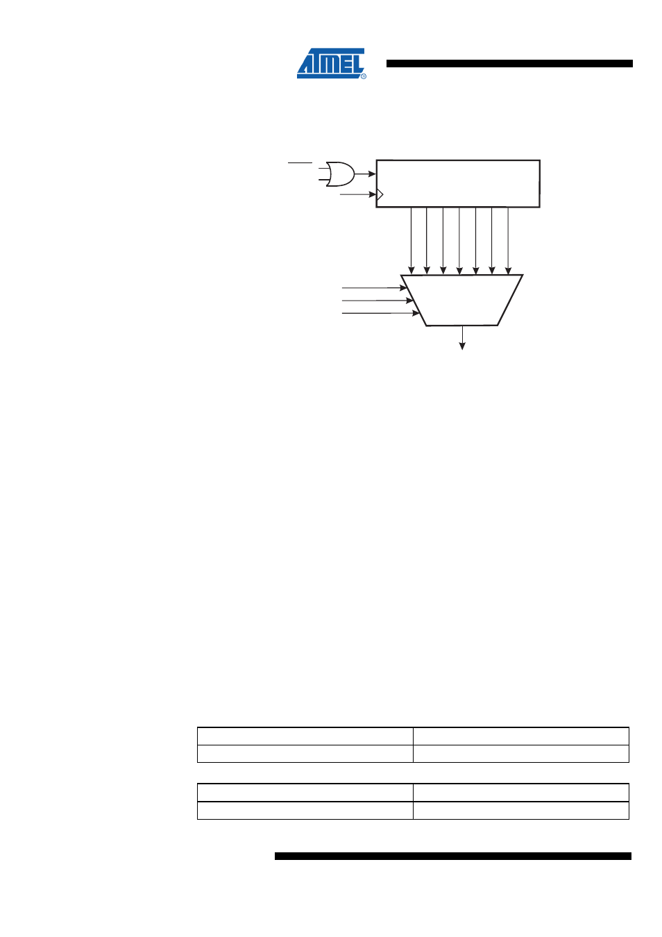
Figure 27-3. ADC Prescaler
7-BIT ADC PRESCALER
ADC CLOCK SOURCE
CK
ADPS0
ADPS1
ADPS2
CK/128
CK/2
CK/4
CK/8
CK/16
CK/32
CK/64
Reset
ADEN
START
The ADC module contains a prescaler, which generates an acceptable ADC clock
frequency from any CPU frequency above 100 kHz. The pre-scaling is set by the ADPS
bits in ADCSRA. The prescaler starts counting from the moment when the ADC is
enabled. The prescaler keeps running for as long as the ADEN bit is set, and is
continuously reset when ADEN is low.
27.5.2 Start-Up Timing
The ADC is enabled by setting the ADEN bit in ADCSRA. First the analog voltage
regulator is powered up which takes t
AVREG
(see
). A stable AVDD is indicated by the AVDDOK bit in
ADCSRB.
After AVDD has stabilized, the ADC is started. The ADC start-up time has a length of
t
ADSU
and can be adjusted by the Start-Up time bits ADSUT4:0 in ADCSRC. If
differential input channels are used, then an additional initialization period t
AINIT
is
required by the gain amplifier. This period is configured by the Track-And-Hold Time
bits, ADTHT1:0 in ADCSRC. ADSUT4:0 and ADTHT1:0 are fixed numbers of ADC
clock cycles and can be setup for different ADC clock speeds.
The minimum required ADC start-up time is 20 µs. Note that for the maximum ADC
speed of 8 MHz the start-up time can not be set higher than 16 µs in ADSUT4:0. Under
this condition the user has either to ensure that a conversion is not started earlier than
20 µs after the ADC is enabled or the first conversion result should be discarded.
For a summary of start-up times and sequences see
page 415 and
Table 27-1. Start-Up Time, Single Ended Channels
Parameter
Duration in ADC Clock Cycles
ADC Start-Up Time t
ADSU
4(ADSUT+1), minimum 20 µs
Table 27-2. Start-Up Time, Differential Channels
Parameter
Duration in ADC Clock Cycles
ADC Start-Up Time t
ADSU
4(ADSUT+1), minimum 20 µs