9 programming the fuse high bits, 10 programming the extended fuse bits, 11 programming the lock bits – Rainbow Electronics ATmega128RFA1 User Manual
Page 474: Atmega128rfa1
474
8266A-MCU Wireless-12/09
ATmega128RFA1
2. C: Load Data Low Byte. Bit n = “0” programs and bit n = “1” erases the Fuse bit.
3. Give WR
___
a negative pulse and wait for RDY/BSY
___
to go high.
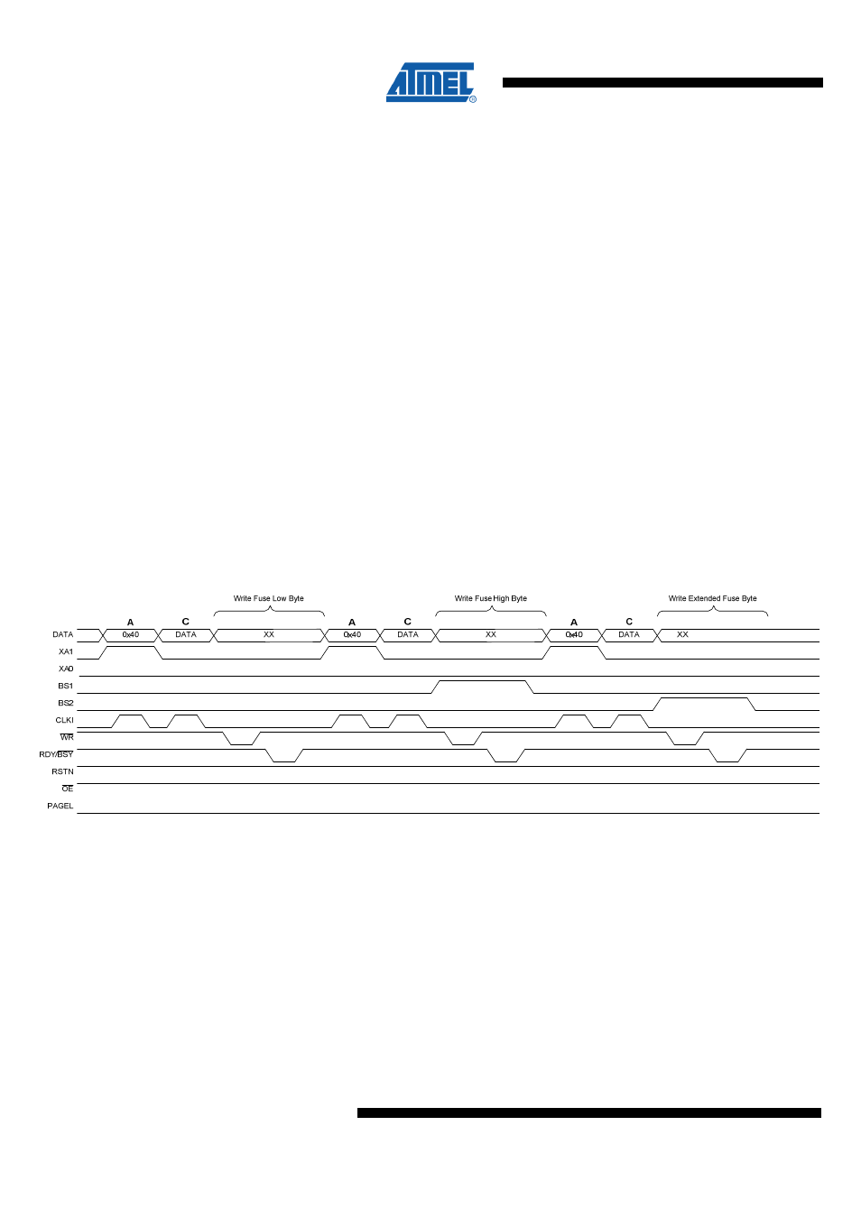
31.7.9 Programming the Fuse High Bits
The algorithm for programming the Fuse High bits is as follows (refer to
page 470 for details on Command and Data loading):
1. A: Load Command “0100 0000”.
2. C: Load Data Low Byte. Bit n = “0” programs and bit n = “1” erases the Fuse bit.
3. Set BS2, BS1 to “01”. This selects high data byte.
4. Give WR
___
a negative pulse and wait for RDY/BSY
___
to go high.
5. Set BS2, BS1 to “00”. This selects low data byte.
31.7.10 Programming the Extended Fuse Bits
The algorithm for programming the Extended Fuse bits is as follows (refer to
page 470 for details on Command and Data loading):
1. A: Load Command “0100 0000”.
2. C: Load Data Low Byte. Bit n = “0” programs and bit n = “1” erases the Fuse bit.
3. Set BS2, BS1 to “10”. This selects extended data byte.
4. Give WR
___
a negative pulse and wait for RDY/BSY
___
to go high.
5. Set BS2, BS1 to “00”. This selects low data byte.
Figure 31-8. Programming the Fuses Waveforms
31.7.11 Programming the Lock Bits
The algorithm for programming the Lock bits is as follows (refer to
page 470 for details on Command and Data loading):
1. A: Load Command “0010 0000”.
2. C: Load Data Low Byte. Bit n = “0” programs the Lock bit. If LB mode 3 is active
(LB1 and LB2 are programmed), it is not possible to program the Boot Lock bits by
any External Programming mode.
3. Give WR
___
a negative pulse and wait for RDY/BSY
___
to go high.
The Lock bits can only be cleared by executing Chip Erase.