1 normal mode, 2 clear timer on compare match (ctc) mode, Atmega128rfa1 – Rainbow Electronics ATmega128RFA1 User Manual
Page 312
312
8266A-MCU Wireless-12/09
ATmega128RFA1
not (inverted or non-inverted PWM). For non-PWM modes the COM2x1:0 bits control
whether the output should be set, cleared, or toggled at a compare match (see chapter
"Compare Match Output Unit" on page 317
).
For detailed timing information refer to chapter
"Timer/Counter Timing Diagrams" on
.
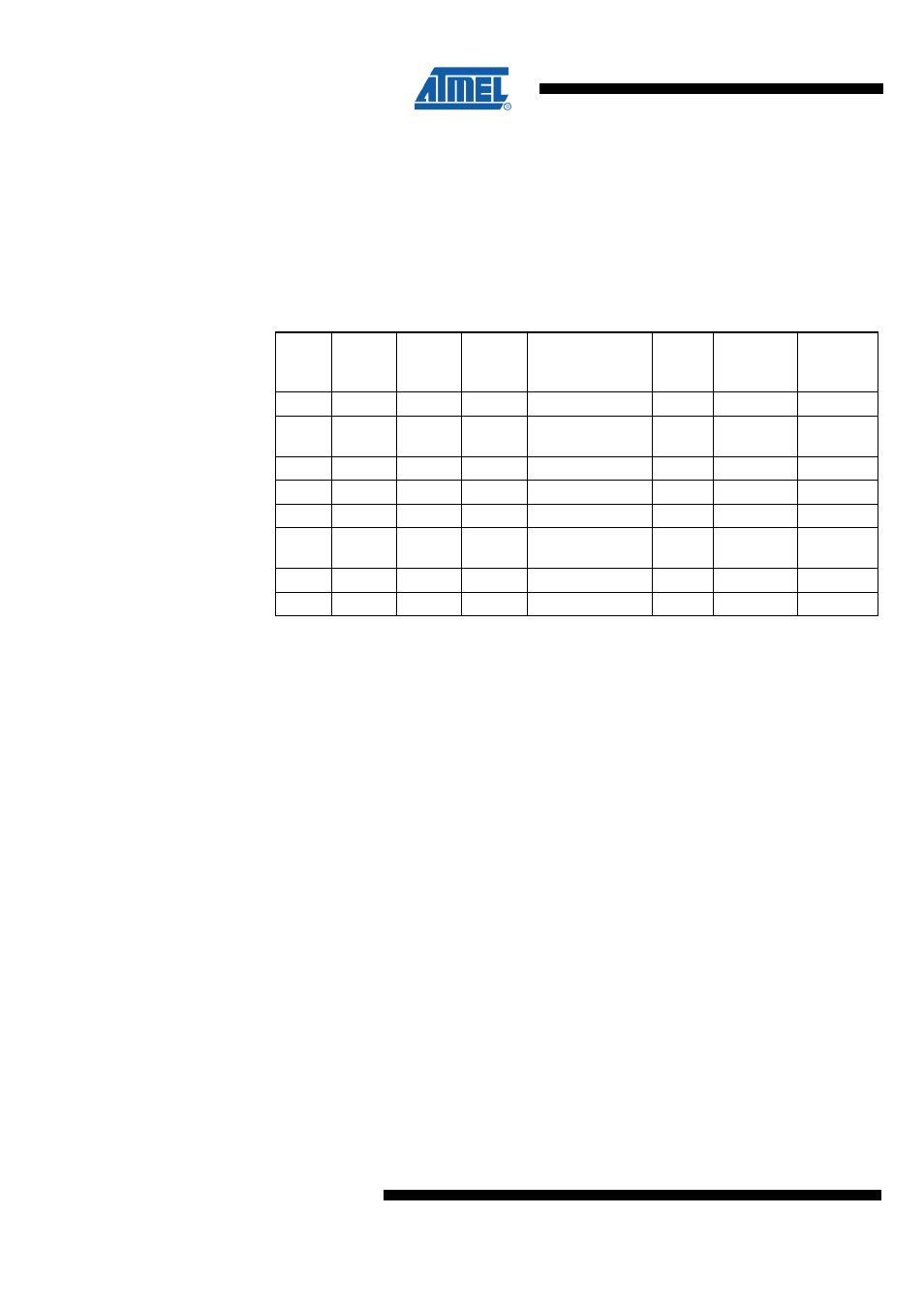
The following table shows the function of the WGM22:0 bits of registers TCCR2A and
TCCR2B. These bits control the counting sequence of the counter, the source for
maximum (TOP) counter value, and what type of waveform generation to be used.
Table 21-2. Waveform Generation Mode Bit Description
Mode
WGM2
WGM1
WGM0
Timer/Counter
Mode of
Operation
TOP
Update of
OCRX at
TOV Flag
Set on
(1,2)
0
0
0
0
Normal
0xFF
Immediate
MAX
1
0
0
1
PWM, Phase
Correct
0xFF
TOP
BOTTOM
2
0
1
0
CTC
OCRA
Immediate
MAX
3
0
1
1
Fast PWM
0xFF
TOP
MAX
4
1
0
0
Reserved
–
–
–
5
1
0
1
PWM, Phase
Correct
OCRA
TOP
BOTTOM
6
1
1
0
Reserved
–
–
–
7
1
1
1
Fast PWM
OCRA
BOTTOM
TOP
Notes:
1. MAX = 0xFF
2. BOTTOM = 0x00
21.5.1 Normal Mode
The simplest mode of operation is the Normal mode (WGM22:0 = 0). In this mode the
counting direction is always up (incrementing), and no counter clear is performed. The
counter simply overruns when it passes its maximum 8 bit value (TOP = 0xFF) and then
restarts from the bottom (0x00). In normal operation the Timer/Counter Overflow Flag
(TOV2) will be set in the same timer clock cycle as the TCNT2 becomes zero. The
TOV2 Flag in this case behaves like a ninth bit, except that it is only set, not cleared.
However combined with the timer overflow interrupt that automatically clears the TOV2
Flag, the timer resolution can be increased by software. There are no special cases to
consider in the Normal mode, a new counter value can be written anytime.
The Output Compare unit can be used to generate interrupts at some given time. Using
the Output Compare to generate waveforms in Normal mode is not recommended,
since this will occupy too much of the CPU time.
21.5.2 Clear Timer on Compare Match (CTC) Mode
In Clear Timer on Compare or CTC mode (WGM22:0 = 2), the OCR2A Register is used
to manipulate the counter resolution. In CTC mode the counter is cleared to zero when
the counter value (TCNT2) matches the OCR2A. The OCR2A defines the top value for
the counter, hence also its resolution. This mode allows greater control of the compare
match output frequency. It also simplifies the operation of counting external events.
The timing diagram for the CTC mode is shown in Table 20-3. The counter value
(TCNT2) increases until a compare match occurs between TCNT2 and OCR2A, and
then counter (TCNT2) is cleared.