1 normal mode, 2 clear timer on compare match (ctc) mode, Atmega128rfa1 – Rainbow Electronics ATmega128RFA1 User Manual
Page 257
257
8266A-MCU Wireless-12/09
ATmega128RFA1
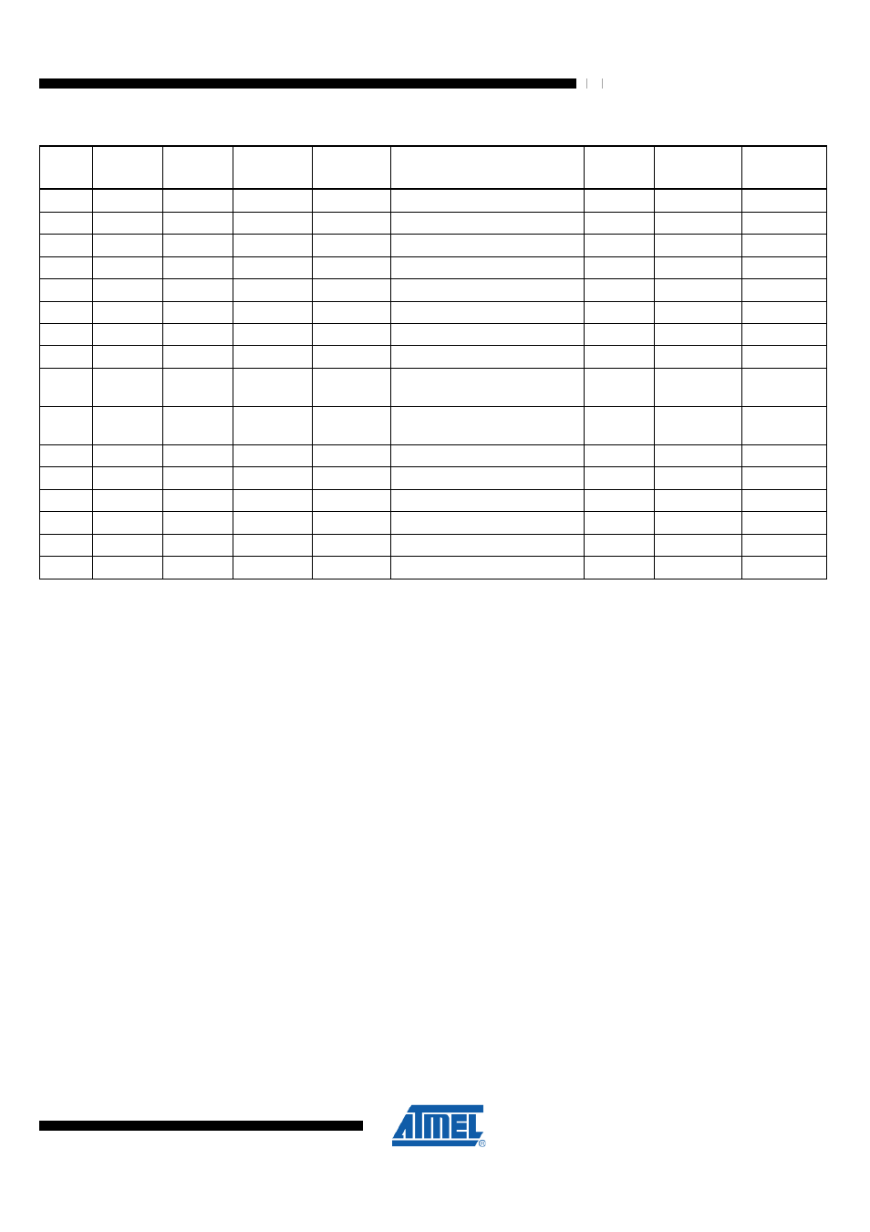
Table 18-5. Waveform Generation Mode Bit Description
(1)
Mode
WGMn3
WGMn2
(CTCn)
WGMn1
(PWMn1)
WGMn0)
(PWMn0)
Timer/Counter
Mode of Operation
TOP
Update of
OCRnx at
TOVn Flag
Set on
0
0
0
0
0
Normal
0xFFFF
Immediate
MAX
1
0
0
0
1
PWM, Phase Correct, 8-bit
0x00FF
TOP
BOTTOM
2
0
0
1
0
PWM, Phase Correct, 9-bit
0x01FF
TOP
BOTTOM
3
0
0
1
1
PWM, Phase Correct, 10-bit
0x3FF
TOP
BOTTOM
4
0
1
0
0
CTC
OCRnA
Immediate
MAX
5
0
1
0
1
Fast PWM, 8-bit
0x00FF
BOTTOM
TOP
6
0
1
1
0
Fast PWM, 9-bit
0x01FF
BOTTOM
TOP
7
0
1
1
1
Fast PWM, 10-bit
0x03FF
BOTTOM
TOP
8
1
0
0
0
PWM, Phase and Frequency
Correct
ICRn
BOTTOM
BOTTOM
9
1
0
0
1
PWM, Phase and Frequency
Correct
OCRnA
BOTTOM
BOTTOM
10
1
0
1
0
PWM, Phase Correct
ICRn
TOP
BOTTOM
11
1
0
1
1
PWM, Phase Correct
OCRnA
TOP
BOTTOM
12
1
1
0
0
CTC
ICRn
Immediate
MAX
13
1
1
0
1
(Reserved)
–
–
–
14
1
1
1
0
Fast PWM
ICRn
BOTTOM
TOP
15
1
1
1
1
Fast PWM
OCRnA
BOTTOM
TOP
Notes:
1. The CTCn and PWMn1:0 bit definition names are obsolete. Use the WGMn2:0 definitions. However, the functionality
and location of these bits are compatible with previous versions of the timer.
For detailed timing information refer to
"Timer/Counter Timing Diagrams" on page 264
.
18.9.1 Normal Mode
The simplest mode of operation is the Normal mode (WGMn3:0 = 0). In this mode the
counting direction is always up (incrementing) and no counter clear is performed. The
counter simply overruns when it passes its maximum 16-bit value (MAX = 0xFFFF) and
then restarts from the BOTTOM (0x0000). In normal operation the Timer/Counter
Overflow Flag (TOVn) will be set in the same timer clock cycle as the TCNTn becomes
zero. In this case the TOVn Flag behaves like a 17
th
bit, except that it is only set and not
cleared. However the timer resolution can be increased by software when combined
with the timer overflow interrupt that automatically clears the TOVn Flag. There are no
special cases to consider in the Normal mode. A new counter value can be written
anytime.
The Input Capture unit is easy to use in Normal mode. However it is important to note
that the maximum interval between the external events must not exceed the resolution
of the counter. The timer overflow interrupt or the prescaler must be used to extend the
resolution for the capture unit if the intervals between events are too long.
The Output Compare units can be used to generate interrupts at some given time.
Using the Output Compare to generate waveforms in Normal mode is not
recommended because this will occupy too much CPU time.
18.9.2 Clear Timer on Compare Match (CTC) Mode
In Clear Timer on Compare (CTC) mode (WGMn3:0 = 4 or 12), the OCRnA or ICRn
Register are used to manipulate the counter resolution. In CTC mode the counter is