11 system clock and clock options, 1 overview, 2 clock systems and their distribution – Rainbow Electronics ATmega128RFA1 User Manual
Page 147: 1 cpu clock - clkcpu, System clock, Atmega128rfa1
147
8266A-MCU Wireless-12/09
ATmega128RFA1
11 System Clock and Clock Options
This section describes the clock options for the AVR microcontroller.
11.1 Overview
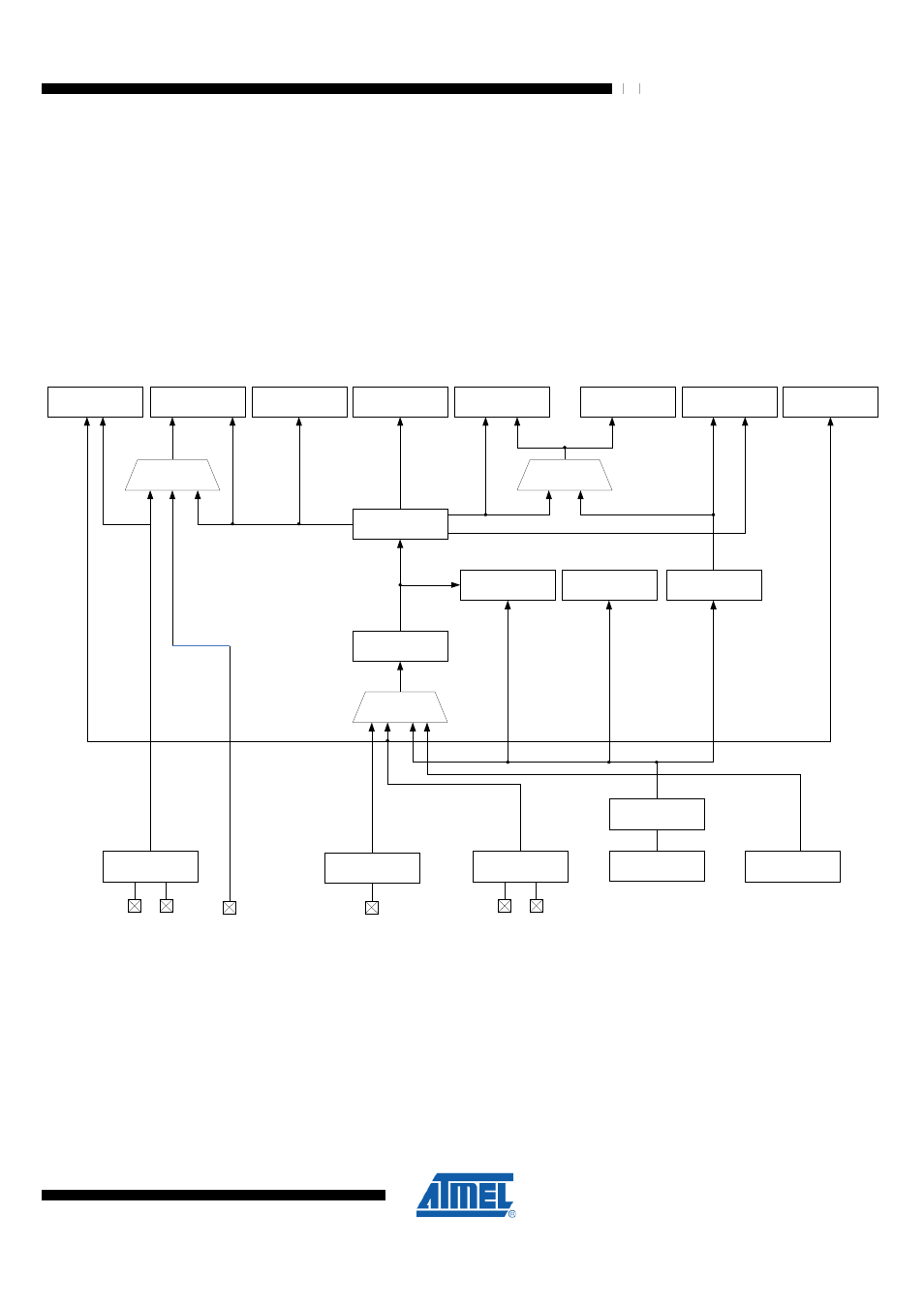
presents the principal clock systems in the AVR and their
distribution. All of the clocks need not be active at a given time. In order to reduce
power consumption, the clocks to modules not being used can be halted by using
different sleep modes, as described in chapter
"Power Management and Sleep Modes"
. The clock systems are detailed below.
Figure 11-1. Clock Distribution
Asynchronous
Timer
General I/O
Modules
ADC
CPU Core
RAM
Flash and
EEPROM
Radio
Transceiver
AVR Clock
Control Unit
System Clock
Prescaler
Reset Logic
Watchdog Timer
Timer/Counter
Oscillator
(32.768kHz)
Transceiver Crystal
Oscillator
(16MHz)
Calibrated RC
Oscillator (16MHz)
Watchdog Oscillator
(128kHz)
T
O
S
C
1
T
O
S
C
2
X
T
A
L
1
X
T
A
L
2
Clock
Multiplexer
1/16 Clock Prescaler
Clock
Multiplexer
Clock
Multiplexer
cp2core
c
p
2
a
d
c
cp2io
c
p
2
e
x
t
cp2ramregf
cp2calib
cp2flash
Source clock
cp2wdt
External Clock
C
L
K
I
1:2
Prescaler
Symbol
Counter
A
M
R
11.2 Clock Systems and their Distribution
11.2.1 CPU Clock – clk
CPU
The CPU clock is routed to parts of the system concerned with operation of the AVR
core. Examples of such modules are the General Purpose Register File, the Status
Register and the data memory holding the Stack Pointer. Halting the CPU clock inhibits
the core from performing general operations and calculations.