2 i/o clock - clki/o, 3 flash clock - clkflash, 4 asynchronous timer clock - clkasy – Rainbow Electronics ATmega128RFA1 User Manual
Page 148: 5 adc clock - clkadc, 3 clock sources, 1 default clock source, 2 clock start-up sequence, Atmega128rfa1
148
8266A-MCU Wireless-12/09
ATmega128RFA1
11.2.2 I/O Clock – clk
I/O
The I/O clock is used by the majority of the I/O modules, like Timer/Counters, SPI, and
USART. The I/O clock is also used by the External Interrupt module, but note that some
external interrupts are detected by asynchronous logic, allowing such interrupts to be
detected even if the I/O clock is halted. Also note that start condition detection in the 2-
wire serial interface (TWI) module is carried out asynchronously when clk
I/O
is halted.
Similar the TWI address recognition in all sleep modes also occurs asynchronously.
11.2.3 Flash Clock – clk
FLASH
The Flash clock controls operation of the Flash interface. The Flash clock is usually
active simultaneously with the CPU clock.
11.2.4 Asynchronous Timer Clock – clk
ASY
The Asynchronous Timer clock allows the Asynchronous Timer/Counter to be clocked
directly from an external clock or an external 32 kHz clock crystal. The dedicated clock
domain allows using this Timer/Counter as a real-time counter even if the device is in
sleep mode.
11.2.5 ADC Clock – clkADC
The ADC is provided with a dedicated clock domain. This allows halting the CPU and
I/O clocks in order to reduce noise generated by digital circuitry. This gives more
accurate ADC conversion results.
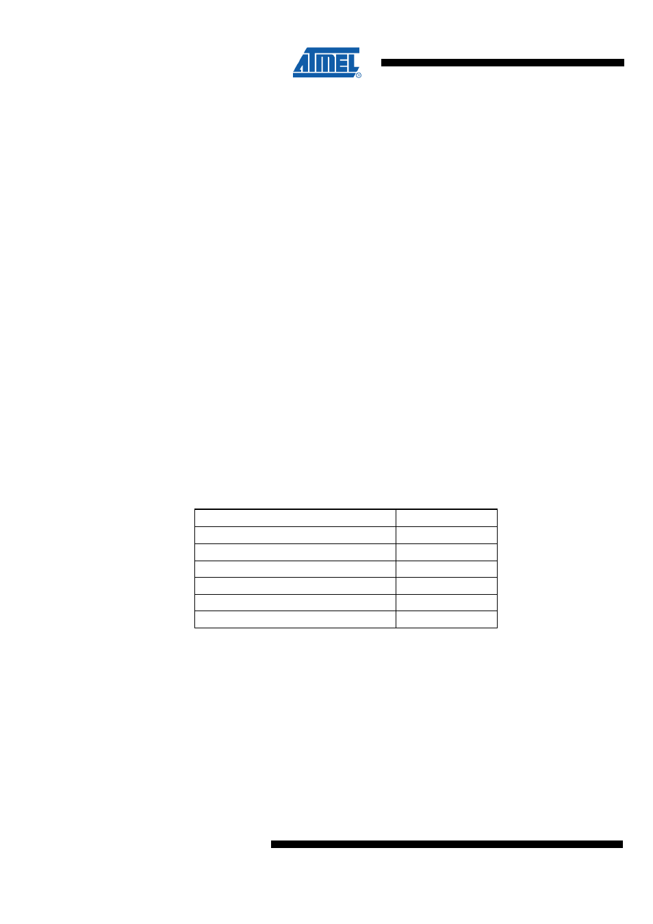
11.3 Clock Sources
The device has the following clock source options, selectable by Flash Fuse bits as
shown below. The clock from the selected source is input to the AVR clock generator,
and routed to the appropriate modules.
Table 11-1. Device Clocking Options Select
(1)
Device Clocking Option
CKSEL3:0
Transceiver clock
1111 – 0110
Reserved
0101 - 0100
Internal 128 kHz RC Oscillator
0011
Calibrated Internal RC Oscillator
0010
External Clock
0000
Reserved
0001
Notes:
1. For all fuses “1” means unprogrammed while “0” means programmed.
11.3.1 Default Clock Source
The device is shipped with internal RC oscillator at 16.0 MHz, the 1:2 prescaler enabled
and with the fuse CKDIV8 programmed, resulting in 1.0 MHz system clock. The startup
time is set to maximum time. (CKSEL = "0010", SUT = "10", CKDIV8 = "0"). The default
setting ensures that all users can make their desired clock source setting using any
available programming interface.
11.3.2 Clock Start-up Sequence
Any clock source needs a minimum number of oscillating cycles before it can be
considered stable.