2 user accessible frame content, User, Atmega128rfa1 – Rainbow Electronics ATmega128RFA1 User Manual
Page 78
78
8266A-MCU Wireless-12/09
ATmega128RFA1
Alternatively Dynamic Frame Buffer Protection can be used to protect received frames
against overwriting. For details refer to
"Dynamic Frame Buffer Protection" on page 91
.
Both procedures do not protect the Frame Buffer from overwriting by the application
software.
In Extended Operating Mode during TX_ARET operation (see
Transmit with Automatic Retry and CSMA-CA Retry" on page 57
)
the radio transceiver
switches to receive if an acknowledgement of a previously transmitted frame was
requested. During this period received frames are evaluated but not stored in the Frame
Buffer. This allows the radio transceiver to wait for an acknowledgement frame and
retry the frame transmission without writing the frame data to the Frame Buffer again.
A radio transceiver state change except a transition to radio transceiver SLEEP state or
a radio transceiver RESET does not affect the Frame Buffer content. The Frame Buffer
is powered off and the stored data gets lost if the radio transceiver is forced into radio
transceiver SLEEP state.
Access conflicts may occur when reading and writing data simultaneously at the two
independent ports of the Frame Buffer TX/RX BBP and Controller interface.
9.6.3.2 User accessible Frame Content
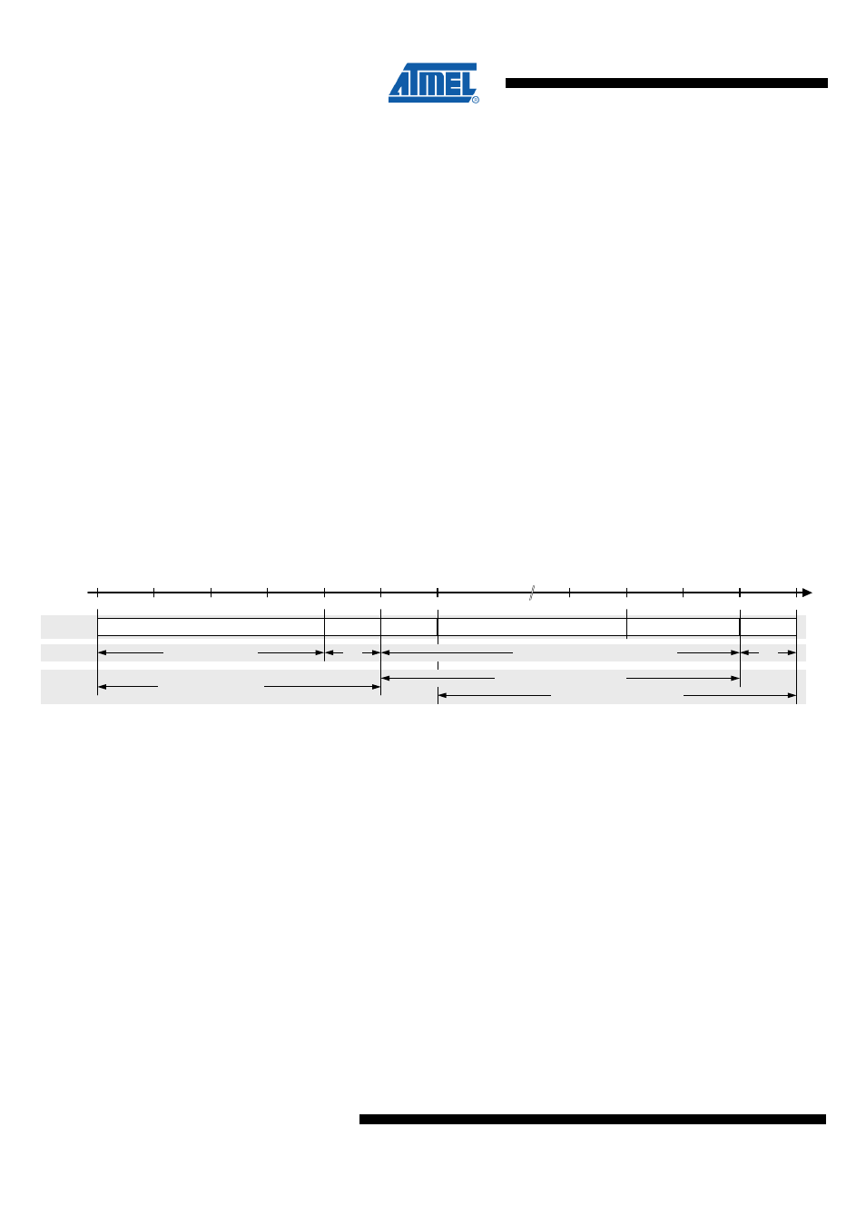
The radio transceiver supports an IEEE 802.15.4 compliant frame format as shown in
the following figure.
Figure 9-31. Transceiver Frame Structure
Preamble Sequence
SFD
PHR
(1)
Payload
LQI
(2)
FCS
0
4
5
6
y + 3
y + 5
y + 6
Frame
Access
SHR not accesible
RX: Frame Buffer content
PHY generated
Length [octets]
Duration
4 octets / 128 µs
1
y
octets / y • 32 µs (y <= 128)
1
TX: Frame Buffer content
Notes: 1. Stored into Frame Buffer for TX operation
2. Stored into Frame Buffer during frame reception.
A frame comprises two sections. The radio transceiver internally generated SHR field
and the user accessible part are stored in the Frame Buffer. The SHR contains the
preamble and the SFD field. The variable frame section contains the PHR and the
PSDU including the FCS (see
).
The Frame Buffer content differs depending on the direction of the communication
(receive or transmit). To access the data follow the procedures described in
.
During frame reception, the payload and the link quality indicator (LQI) value of a
successfully received frame are stored in the Frame Buffer. The radio transceiver
appends the LQI value to the frame data after the last received octet. Information of the
frame length is not stored in the Frame Buffer. The frame length information is located
in register TST_RX_LENGTH.
The SHR (except the SFD used to generate the last octet of the SHR) can generally not
be read by the application software.