6 self-programming the flash, Atmega128rfa1 – Rainbow Electronics ATmega128RFA1 User Manual
Page 454
454
8266A-MCU Wireless-12/09
ATmega128RFA1
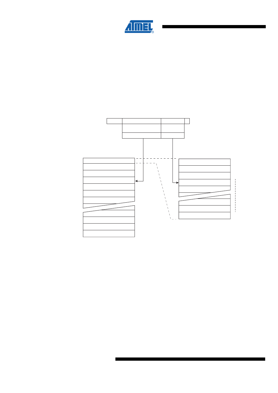
Since the Flash is organized in pages (see
), the Program
Counter can be treated as having two different sections. One section, consisting of the
least significant bits, is addressing the words within a page, while the most significant
bits are addressing the pages. This is shown in
. Note that the Page
Erase and Page Write operations are addressed independently. Therefore it is of major
importance that the Boot Loader software addresses the same page in both the Page
Erase and Page Write operation. Once a programming operation is initiated, the
address is latched and the Z-pointer can be used for other operations.
The (E)LPM instruction uses the Z-pointer to store the address. Since this instruction
addresses the Flash byte-by-byte, also bit Z0 of the Z-pointer is used.
Figure 30-3. Addressing the Flash during SPM
PROGRAM MEMORY
0
1
15
Z - REGISTER
BIT
0
ZPAGEMSB
WORD ADDRESS
WITHIN A PAGE
PAGE ADDRESS
WITHIN THE FLASH
ZPCMSB
INSTRUCTION WORD
PAGE
PCWORD[PAGEMSB:0]:
00
01
02
PAGEEND
PAGE
PCWORD
PCPAGE
PCMSB
PAGEMSB
PROGRAM
COUNTER
Note:
1. The different variables used in
.
30.6 Self-Programming the Flash
The program memory is updated in a page by page fashion. Before programming a
page with the data stored in the temporary page buffer, the page must be erased. The
temporary page buffer is filled one word at a time using SPM and the buffer can be filled
either before the Page Erase command or between a Page Erase and a Page Write
operation:
Alternative 1, fill the buffer before a Page Erase
•
Fill temporary page buffer,
•
Perform a Page Erase,
•
Perform a Page Write;
Alternative 2, fill the buffer after Page Erase
•
Perform a Page Erase,