4 calibration byte, 1 signal names, Table 31-7" on – Rainbow Electronics ATmega128RFA1 User Manual
Page 467: Atmega128rfa1
467
8266A-MCU Wireless-12/09
ATmega128RFA1
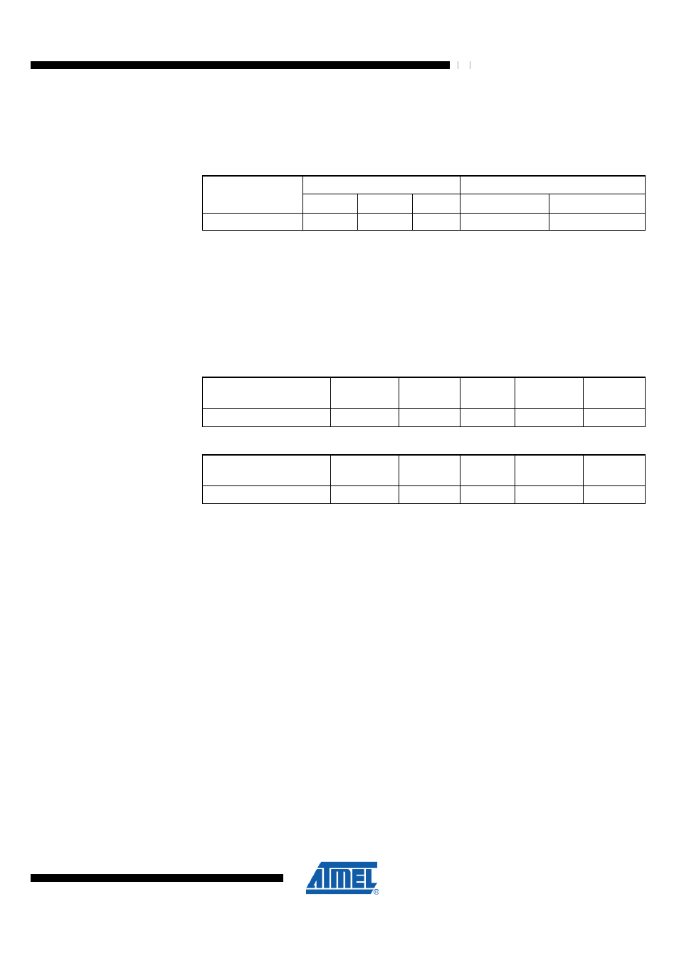
The three bytes reside in a separate address space. For the ATmega128RFA1 the
signature bytes are given in
. Accessing the signature bytes from
software is described in section
"Reading the Signature Row from Software" on page
.
Table 31-6. Device and JTAG ID
Signature Byte Number
JTAG
Part
0
1
2
Part Number
Manufacturer ID
ATmega128RFA1
0x1E
0xA7
0x01
0xA701
0x1F
31.4 Calibration Byte
The ATmega128RFA1 has a byte calibration value for the internal RC Oscillator. This
byte resides in the high byte of address 0x000 in the signature address space. During
reset, this byte is automatically written into the OSCCAL Register to ensure correct
frequency of the calibrated RC Oscillator.
31.5 Page Size
Table 31-7. Number of Words in a Page and Number of Pages in the Flash
Flash Size
Page Size
PCWORD
No. of
Pages
PCPAGE
PCMSB
64k words (128k bytes)
128 words
PC[6:0]
512
PC[15:7]
15
Table 31-8. Number of Bytes in a Page and Number of Pages in the EEPROM
EEPROM Size
Page Size
PCWORD
No. of
Pages
PCPAGE
EEAMSB
4k bytes
8 bytes
EEA[2:0]
512
EEA[11:3]
11
31.6 Parallel Programming Parameters, Pin Mapping, and Commands
This section describes how to parallel program and verify Flash Program memory,
EEPROM Data memory, Memory Lock bits, and Fuse bits in the ATmega128RFA1.
31.6.1 Signal Names
In this section, some pins of the ATmega128RFA1 are referenced by signal names
describing their functionality during parallel programming; see
page 468. Pins not described in this table are referenced by their
default pin names.
The XA1/XA0 pins determine the action executed when the CLKI pin is given a positive
pulse. The bit coding is shown in
When pulsing WR
___
or OE
__
or, the command loaded determines the action executed. The