3 timer/counter clock sources, Figure 21-1 on, Atmega128rfa1 – Rainbow Electronics ATmega128RFA1 User Manual
Page 310
310
8266A-MCU Wireless-12/09
ATmega128RFA1
register or bit defines in a program, the precise form must be used, i.e., TCNT2 for
accessing Timer/Counter2 counter value and so on.
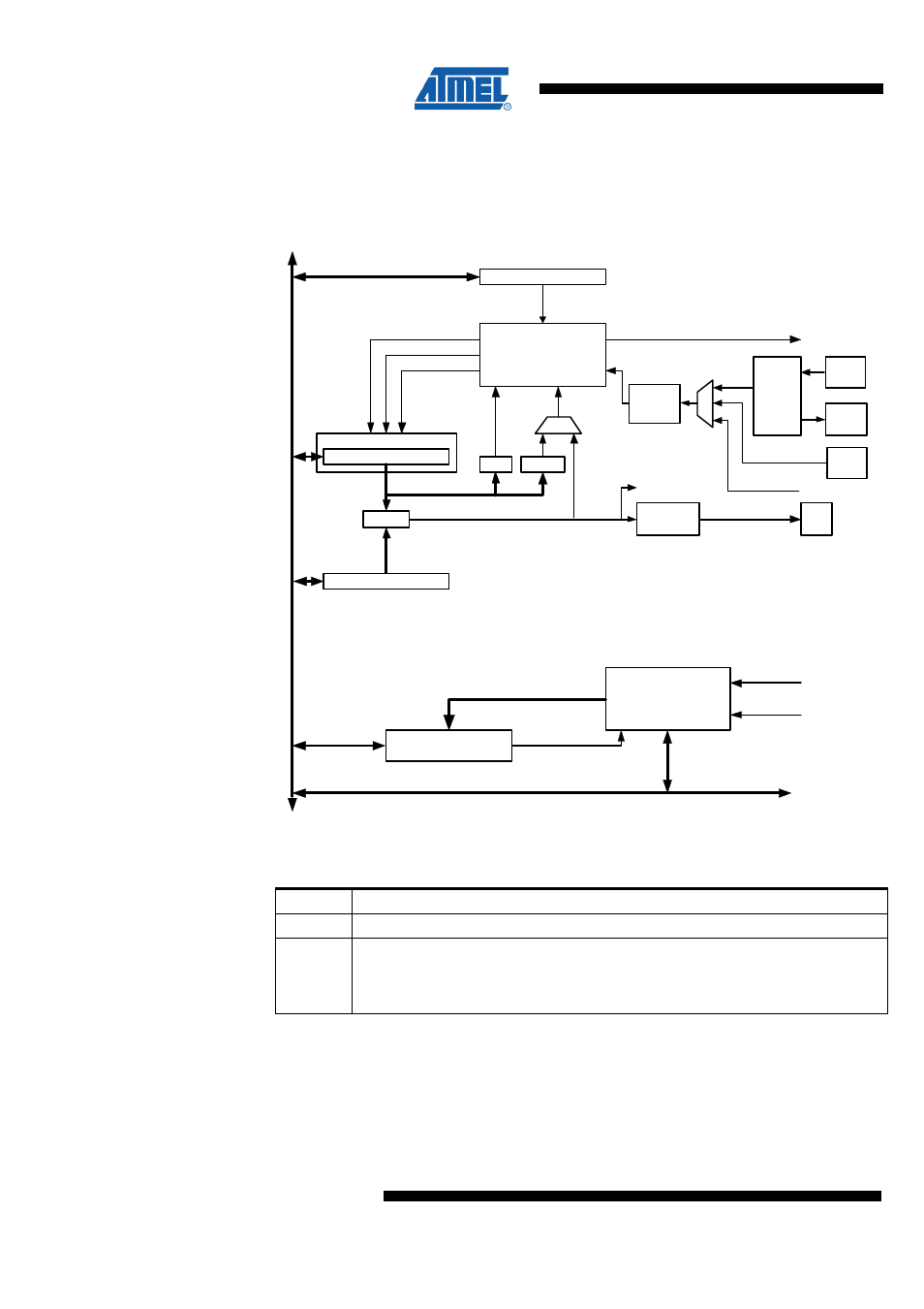
Figure 21-1. 8-bit Timer/Counter Block Diagram
Timer/Counter
D
A
T
A
B
U
S
=
TCNTn
Waveform
Generation
OCnx
= 0
Control Logic
= 0x F F
TOP
BOTTOM
count
clear
direction
TOVn
(Int.Req.)
OCnx
(Int.Req.)
Synchronization Unit
OCRnx
TCCRnx
ASSRn
Status flags
clkI/O
clkASY
Synchronized Status flags
asynchronous mode
select (ASn)
TOSC1
T/C
Oscillator
TOSC2
Prescaler
clkTn
clkI/O
AMR
are also used extensively throughout the
section.
Table 21-1. Definitions
BOTTOM The counter reaches the BOTTOM when it becomes zero (0x00).
MAX
The counter reaches its MAXimum when it becomes 0xFF (decimal 255).
TOP
The counter reaches the TOP when it becomes equal to the highest value in the
count sequence. The TOP value can be assigned to be the fixed value 0xFF (MAX)
or the value stored in the OCR2A Register. The assignment is dependent on the
mode of operation.
21.3 Timer/Counter Clock Sources
The Timer/Counter can be clocked by an internal synchronous or an external
asynchronous clock source. The clock source clk
T2
is by default equal to the MCU
clock, clk
I/O
. When the AS2 bit in the ASSR Register is written to logic one, the clock
source is either taken from the Timer/Counter Oscillator connected to TOSC1 and
TOSC2 or from the AMR pin. For details on asynchronous operation, see section