2 operation, Atmega128rfa1 – Rainbow Electronics ATmega128RFA1 User Manual
Page 411
411
8266A-MCU Wireless-12/09
ATmega128RFA1
The Power Reduction ADC bit, PRADC (see
"PRR0 – Power Reduction Register0" on
) must be disabled by writing a logical zero to enable the ADC.
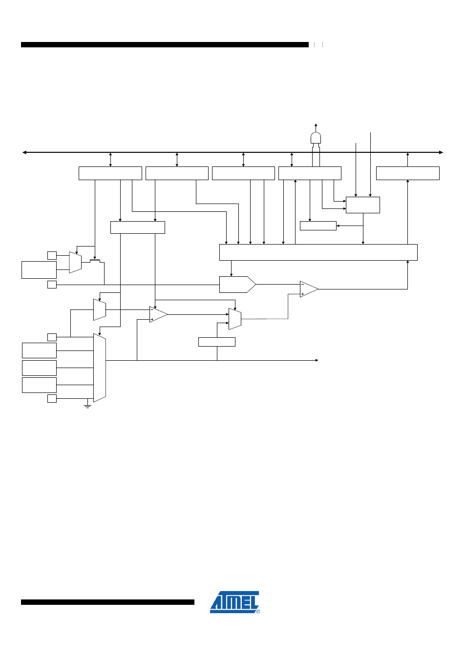
Figure 27-1. Analog to Digital Converter Block Schematic
8-BIT D ATABU S
AD C CTRL & STATUS
R EGISTER B (ADC SR B)
AD C C TRL & STATU S
REG ISTER C (ADC SR C)
ADC MULTIPLEXER
SELECT (ADMU X)
AD C C TRL & STATUS
REGISTER A (AD CSR A)
TRIGGER
SELECT
A
D
F
R
A
D
S
C
ADTS [2:0]
INTE RRUP T
FLAGS
A
D
IF
A
D
IE
AD C ON VER SION
C OMPLETE IRQ
AD C DATA R EG ISTER
(ADC H/AD CL)
15
0
PR ESC ALER
C ON VER SION LOGIC
STA RT
A
D
P
S
[2
:0
]
A
D
IF
A
D
E
N
A
D
C
[9
:0
]
A
D
S
U
T
[4
:0
]
A
D
T
H
T
[1
:0
]
A
D
L
A
R
M UX D EC ODER
M
U
X
[4
:0
]
M
U
X
[5
]
R
E
F
S
[1
:0
]
C
H
A
N
N
E
L
S
E
L
E
C
T
IO
N
D
IF
F
/
G
A
IN
S
E
L
E
C
T
10-bit DAC
SAMPLE & H OLD
CO MPARATOR
AVD D
AREF
INTERNAL
REFERENCE
(1.5V/1.6V)
AD C[7:0]
AVSS
BA NDGAP
REFERE NCE
1.2V
TEM PE RA TURE
S ENS OR
ADC[2:0]
GAIN
AMPLIFIER
AD C
MULTIPLEXER
OUTPUT
DRT VO LTA GE
SRAM 2
CLAMP
A
C
C
H
27.2 Operation
The ADC converts an analog input voltage to a 10-bit digital value through successive
approximation. The minimum value represents 0V (conversion result 0x000) and the
maximum value in single ended mode represents the reference voltage minus 1 LSB
(conversion result 0x3FF). The reference voltage can be measured at the AREF pin.
The internal, generated reference voltage can have the values 1.5V, 1.6V or AVDD
where the 1.6V has the highest absolute accuracy. The reference voltage is selected by
writing to the REFSn bits in the ADMUX Register. An external reference voltage can
also be selected. Such an external voltage must be supplied with a very low impedance
R
AREF,EXT
"ADC Electrical Characteristics" on page 505
). The load current I
L,AREF
"ADC Electrical Characteristics" on page 505
) seen by the external source is code
dependent and changes in the course of the successive approximation process (load
current steps). The internal voltage reference (except AVDD) must not be decoupled by
an external capacitor. Adding unnecessary external capacitance at the AREF pin will