2 avr_reset (0xc), 3 prog_enable (0x4), Figure 31-16 on – Rainbow Electronics ATmega128RFA1 User Manual
Page 482: Atmega128rfa1
482
8266A-MCU Wireless-12/09
ATmega128RFA1
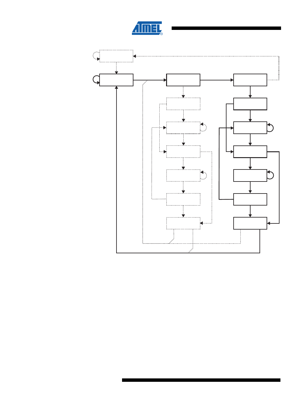
Figure 31-16. State Machine Sequence for Changing the Instruction Word
Test-Logic-Reset
Run-Test/Idle
Shift-DR
Exit1-DR
Pause-DR
Exit2-DR
Update-DR
Select-IR Scan
Capture-IR
Shift-IR
Exit1-IR
Pause-IR
Exit2-IR
Update-IR
Select-DR Scan
Capture-DR
0
1
0
1
1
1
0
0
0
0
1
1
1
0
1
1
0
1
0
0
1
0
1
1
0
1
0
0
0
0
1
1
31.9.2 AVR_RESET (0xC)
The AVR specific public JTAG instruction is used for setting the AVR device in the
Reset mode or taking the device out from the Reset mode. The TAP-controller is not
reset by this instruction. The one bit Reset Register is selected as Data Register. Note
that the reset will be active as long as there is a logic “one” in the Reset Chain. The
output from this chain is not latched.
The active states are:
•
Shift-DR: The Reset Register is shifted by the TCK input.
31.9.3 PROG_ENABLE (0x4)
The AVR specific public JTAG instruction enables programming via the JTAG port. The
16-bit Programming Enable Register is selected as Data Register. The active states are
the following:
•
Shift-DR: The programming enable signature is shifted into the Data Register.