3 conversion timing, Figure 27-4 on, Figure 27-5 on – Rainbow Electronics ATmega128RFA1 User Manual
Page 415: Atmega128rfa1
415
8266A-MCU Wireless-12/09
ATmega128RFA1
Parameter
Duration in ADC Clock Cycles
Gain Amplifier Initialization Time t
AINIT
2(ADTHT+2)
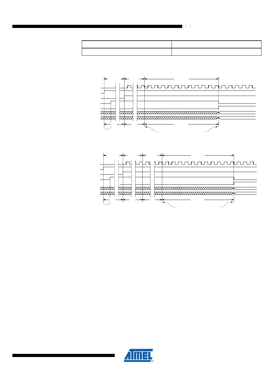
Figure 27-4. ADC Timing Diagram, Start-Up for Single Ended Channels
A D C C lo c k
A D E N
A D S C
A V D D O K
A D IF
A D C H
A D C L
A D C
S t a r t - U p
t
A V P U
t
A D S U
M U X a n d R E F S U p d a te
1 1 T
A D C _ C L K
C o n v e r s io n
A V D D
P o w e r - U p
S ig n a n d M S B o f R e s u lt
L S B o f R e s u lt
S a m p le
& H o ld
C o n v e r s io n
C o m p le te
Figure 27-5. ADC Timing Diagram, Start-Up for Differential Channels
A D C C lo c k
A D E N
A D S C
A V D D O K
A D IF
A D C H
A D C L
A D C
S ta r t -U p
t
A V P U
t
A D S U
M U X a n d R E F S U p d a te
1 1 T
A D C _ C L K
C o n v e r s io n
A V D D
P o w e r -U p
S ig n a n d M S B
L S B o f R e s u lt
S a m p le
& H o ld
C o n v e rs io n
C o m p le te
A m p lifie r
In it
t
A IN IT
27.5.3 Conversion Timing
The delay from requesting a conversion start by setting the ADSC bit in ADCSRA to the
moment where the sample-and-hold takes place is fixed. The same fixed delay also
applies for auto triggered conversions. In this case three additional CPU clock cycles
are used for the trigger event synchronization logic. The delay depends on the
prescaler configuration ADPS and if single-ended or differential channels are used. A
summary is given in
page 416. All conversions take 11 ADC clock cycles.
When a conversion is complete, the result is written to the ADC Data Registers, and
ADIF is set. In Single Conversion mode, ADSC is cleared simultaneously. The software
may then set ADSC again, and a new conversion will be initiated at the earliest after the
following tracking phase. The tracking phase is required after each conversion. Its
duration can be adjusted according to the ADC clock speed by the ADTHT bits in
ADCSRC and is different for single-ended and differential channels. For details see
In Free Running mode, a new conversion will be started immediately after the tracking
phase of the previous conversion while ADSC remains high. The calculation of the
resulting sample rate is given
For timing diagrams of single and auto triggered and free running conversions see
page 416 to