10 ucsr1c - usart1 control and status register c, Atmega128rfa1 – Rainbow Electronics ATmega128RFA1 User Manual
Page 363
363
8266A-MCU Wireless-12/09
ATmega128RFA1
The UCSZ12 bits combined with the UCSZ11:0 bit in UCSR1C sets the number of data
bits (Character Size) in the frame that the Receiver and Transmitter use.
•
Bit 1 – RXB81 - Receive Data Bit 8
RXB81 is the 9th data bit of the received character when operating with serial frames
with nine data bits. The bit must be read before reading the lower 8 bits from UDR1.
•
Bit 0 – TXB81 - Transmit Data Bit 8
TXB81 is the 9th data bit in the character to be transmitted when operating with serial
frames with nine data bits. The bit must be written before writing the lower 8 bits to
UDR1.
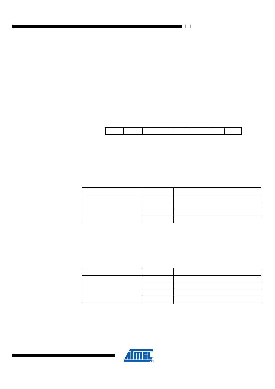
23.10.10 UCSR1C – USART1 Control and Status Register C
Bit
7
6
5
4
3
2
1
0
NA ($CA)
UMSEL11 UMSEL10 UPM11
UPM10
USBS1 UCSZ11 UCSZ10 UCPOL1 UCSR1C
Read/Write
RW
RW
RW
RW
RW
RW
RW
RW
Initial Value
0
0
0
0
0
1
1
0
•
Bit 7:6 – UMSEL11:10 - USART Mode Select
These bits select the mode of operation of the USART1 as shown in the following table.
See section "USART in SPI Mode" for a full description of the Master SPI Mode
(MSPIM) operation.
Table 23-9 UMSEL1 Register Bits
Register Bits
Value
Description
0x00
Asynchronous USART
0x01
Synchronous USART
0x02
Reserved
UMSEL11:10
0x03
Master SPI (MSPIM)
•
Bit 5:4 – UPM11:10 - Parity Mode
These bits enable and set type of parity generation and check. If enabled, the
Transmitter will automatically generate and send the parity of the transmitted data bits
within each frame. The Receiver will generate a parity value for the incoming data and
compare it to the UPM1 setting. If a mismatch is detected, the UPE1 Flag in UCSR1A
will be set.
Table 23-10 UPM1 Register Bits
Register Bits
Value
Description
0x00
Disabled
0x01
Reserved
0x02
Enabled, Even Parity
UPM11:10
0x03
Enabled, Odd Parity
•
Bit 3 – USBS1 - Stop Bit Select
This bit selects the number of stop bits to be inserted by the Transmitter. The Receiver
ignores this setting.