3 fast pwm mode, Atmega128rfa1 – Rainbow Electronics ATmega128RFA1 User Manual
Page 313
313
8266A-MCU Wireless-12/09
ATmega128RFA1
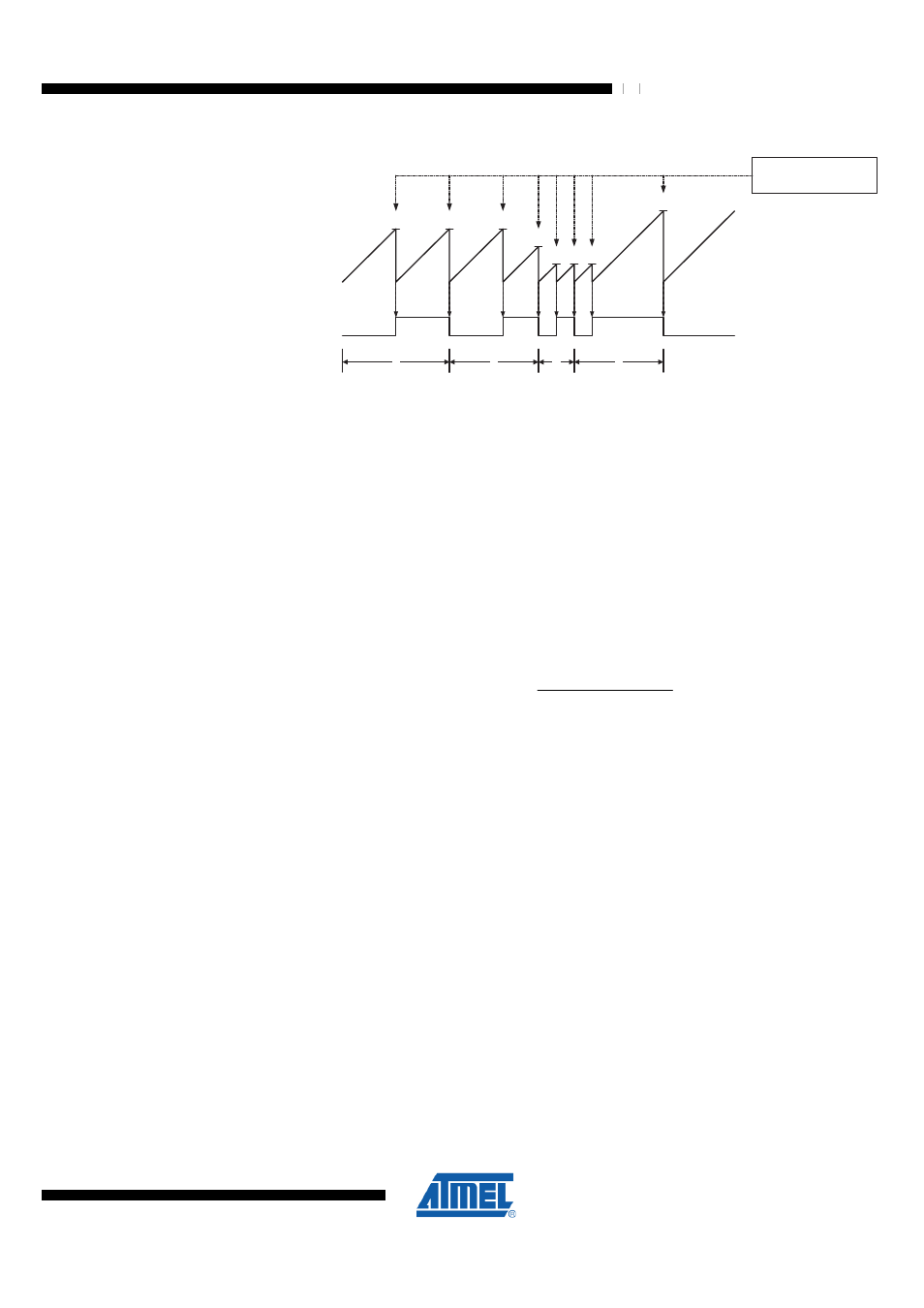
Figure 21-3. CTC Mode, Timing Diagram
TCNTn
OCn
(Toggle)
OCnx Interrupt Flag Set
1
4
Period
2
3
(COMnx1:0 = 1)
An interrupt can be generated each time the counter value reaches the TOP value by
using the OCF2A Flag. If the interrupt is enabled, the interrupt handler routine can be
used for updating the TOP value. However, changing TOP to a value close to BOTTOM
when the counter is running with none or a low prescaler value must be done with care
since the CTC mode does not have the double buffering feature. If the new value
written to OCR2A is lower than the current value of TCNT2, the counter will miss the
compare match. The counter will then have to count to its maximum value (0xFF) and
wrap around starting at 0x00 before the compare match can occur.
For generating a waveform output in CTC mode, the OC2A output can be set to toggle
its logical level on each compare match by setting the Compare Output mode bits to
toggle mode (COM2A1:0 = 1). The OC2A value will not be visible on the port pin unless
the data direction for the pin is set to output. The waveform generated will have a
maximum frequency of f
OC2A
= f
clk_I/O
/2 when OCR2A is set to zero (0x00). The
waveform frequency is defined by the following equation
)
1
(
2
/
_
OCRnx
N
f
f
O
I
clk
OCnx
+
⋅
⋅
=
The N variable represents the pre-scale factor (1, 8, 32, 64, 128, 256, or 1024).
As for the Normal mode of operation, the TOV2 Flag is set in the same timer clock cycle
that the counter counts from MAX to 0x00.
21.5.3 Fast PWM Mode
The Timer/Counter Overflow Flag (TOV2) is set each time the counter reaches TOP. If
the interrupt is enabled, the interrupt handler routine can be used for updating the
compare value.
In fast PWM mode, the compare unit allows generation of PWM waveforms on the
OC2x pin. Setting the COM2x1:0 bits to two will produce a non-inverted PWM and an
inverted PWM output can be generated by setting the COM2x1:0 to three. TOP is
defined as 0xFF when WGM22:0 = 3, and OCR2A when WGM22:0 = 7 (see section
"Register Description" on page 323
for register TCCR2A). The actual OC2x value will
only be visible on the port pin if the data direction for the port pin is set as output. The
PWM waveform is generated by setting (or clearing) the OC2x Register at the compare
match between OCR2x and TCNT2, and clearing (or setting) the OC2x Register at the
timer clock cycle the counter is cleared (changes from TOP to BOTTOM).