12 reading the fuse and lock bits, 13 reading the signature bytes, 14 reading the calibration byte – Rainbow Electronics ATmega128RFA1 User Manual
Page 475: Atmega128rfa1
475
8266A-MCU Wireless-12/09
ATmega128RFA1
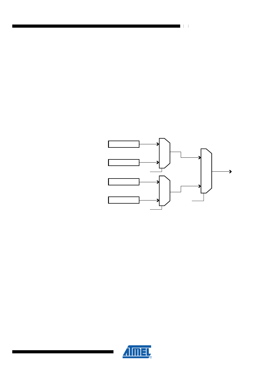
31.7.12 Reading the Fuse and Lock Bits
The algorithm for reading the Fuse and Lock bits is as follows (refer to
page 470 for details on Command and Data loading):
1. A: Load Command “0000 0100”.
2. Set OE
__
to “0”, and BS2, BS1 to “00”. The status of the Fuse Low bits can now be
read at DATA (“0” means programmed).
3. Set OE
__
to “0”, and BS2, BS1 to “11”. The status of the Fuse High bits can now be
read at DATA (“0” means programmed).
4. Set OE
__
to “0”, and BS2, BS1 to “10”. The status of the Extended Fuse bits can now
be read at DATA (“0” means programmed).
5. Set OE
__
to “0”, and BS2, BS1 to “01”. The status of the Lock bits can now be read at
DATA (“0” means programmed).
6. Set OE
__
to “1”.
Figure 31-9. Mapping between BS1, BS2 and the Fuse and Lock Bits during Read
Lock Bits
0
1
BS2
Fuse High Byte
0
1
BS1
DATA
Fuse Low Byte
0
1
BS2
Extended Fuse Byte
31.7.13 Reading the Signature Bytes
The algorithm for reading the Signature bytes is as follows (refer to
page 470 for details on Command and Data loading):
1. A: Load Command “0000 1000”.
2. B: Load Address Low Byte (0x00 - 0x02).
3. Set OE
__
to “0” and BS to “0”. The selected Signature byte can now be read at DATA.
4. Set OE
__
to “1”.
31.7.14 Reading the Calibration Byte
The algorithm for reading the Calibration byte is as follows (refer to
page 470 for details on Command and Data loading):
1. A: Load Command “0000 1000”.
2. B: Load Address Low Byte, 0x00.
3. Set OE
__
to “0” and BS1 to “1”. The Calibration byte can now be read at DATA.
4. Set OE
__
to “1”.