1 power-on reset, Atmega128rfa1 – Rainbow Electronics ATmega128RFA1 User Manual
Page 177
177
8266A-MCU Wireless-12/09
ATmega128RFA1
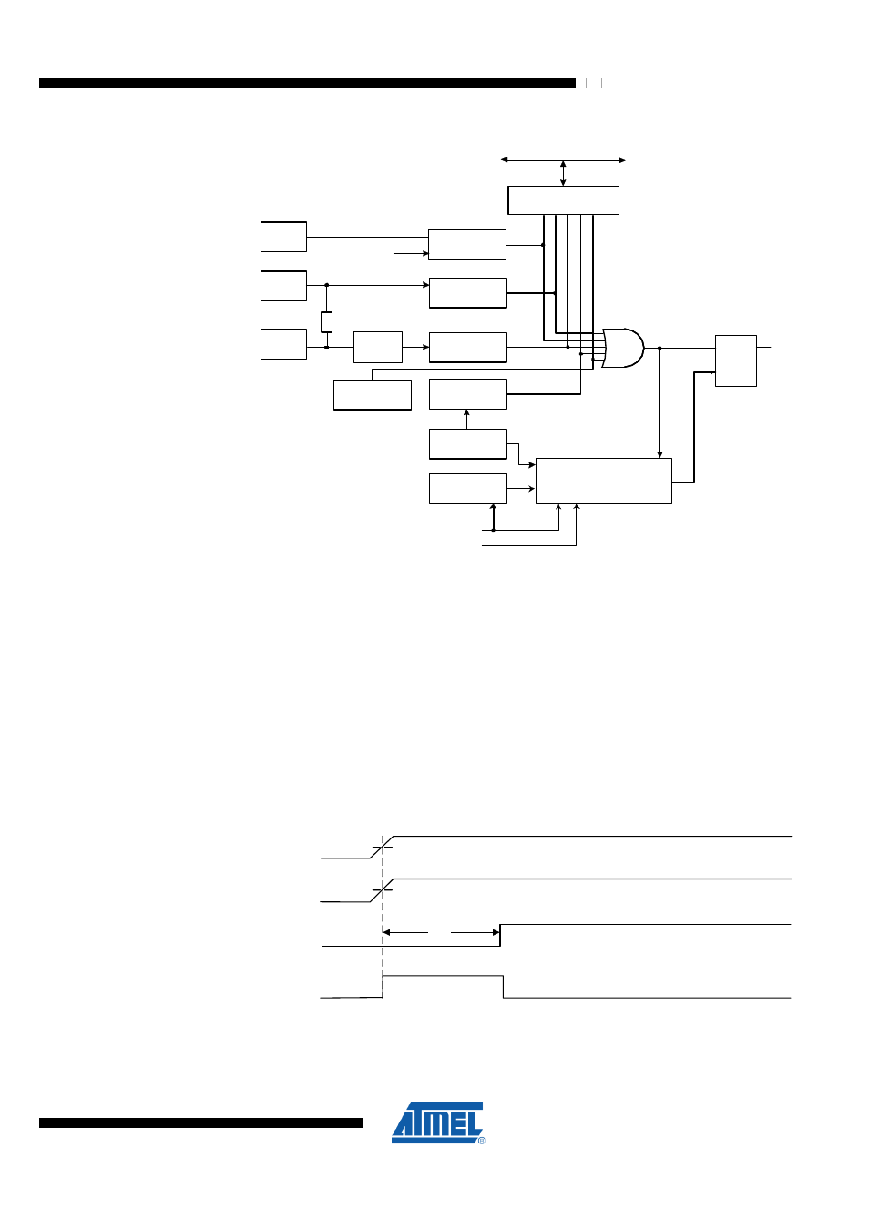
Figure 13-1. Reset Logic
EVDD
RSTN
Delay Counters
S Q
R
MCU Status
Register (MCUSR)
BODLEVEL [2..0]
CKSEL[3:0]
CK
TIMEOUT
W
D
R
F
B
O
R
F
EX
T
R
F
DATA BUS
SPIKE
FILTER
Pull-up Resistor
J
T
R
F
SUT[1:0]
JTAG Reset
Register
Brown-out
Reset Circuit
Power-on
Reset Circuit
Reset Circuit
Watchdog
Timer
Watchdog
Oscillator
Clock
Generator
IN
T
E
R
N
A
L
R
E
S
E
T
C
O
U
N
T
E
R
R
E
S
E
T
P
O
R
F
DEVDD
13.2.1 Power-on Reset
A Power-on Reset (POR) pulse is generated by a dynamic, on-chip detection circuit.
The POR is active when DEVDD is rising. The electrical characteristics are defined in
"System and Reset Characteristics" on page 502
. The POR circuit can be used to
trigger the start-up reset. To detect a failure in the supply voltage (e.g. a voltage drop)
the brown-own detector should be used.
A Power-on Reset (POR) circuit ensures that the device is reset from Power-on.
Reaching the Power-on Reset threshold voltage invokes the delay counter, which
determines how long the device is kept in RESET after the DEVDD rise. The RESET
signal is activated again without any delay, when DEVDD decreases below the
detection level.
Figure 13-2. MCU Start-up, RSTN Tied to DEVDD
DEVDD
RSTN
TIME-OUT
INTERNAL
RESET
V
POT
V
RST
t
TOUT