Brocade Mobility Access Point System Reference Guide (Supporting software release 5.5.0.0 and later) User Manual
Page 106
96
Brocade Mobility Access Point System Reference Guide
53-1003100-01
5
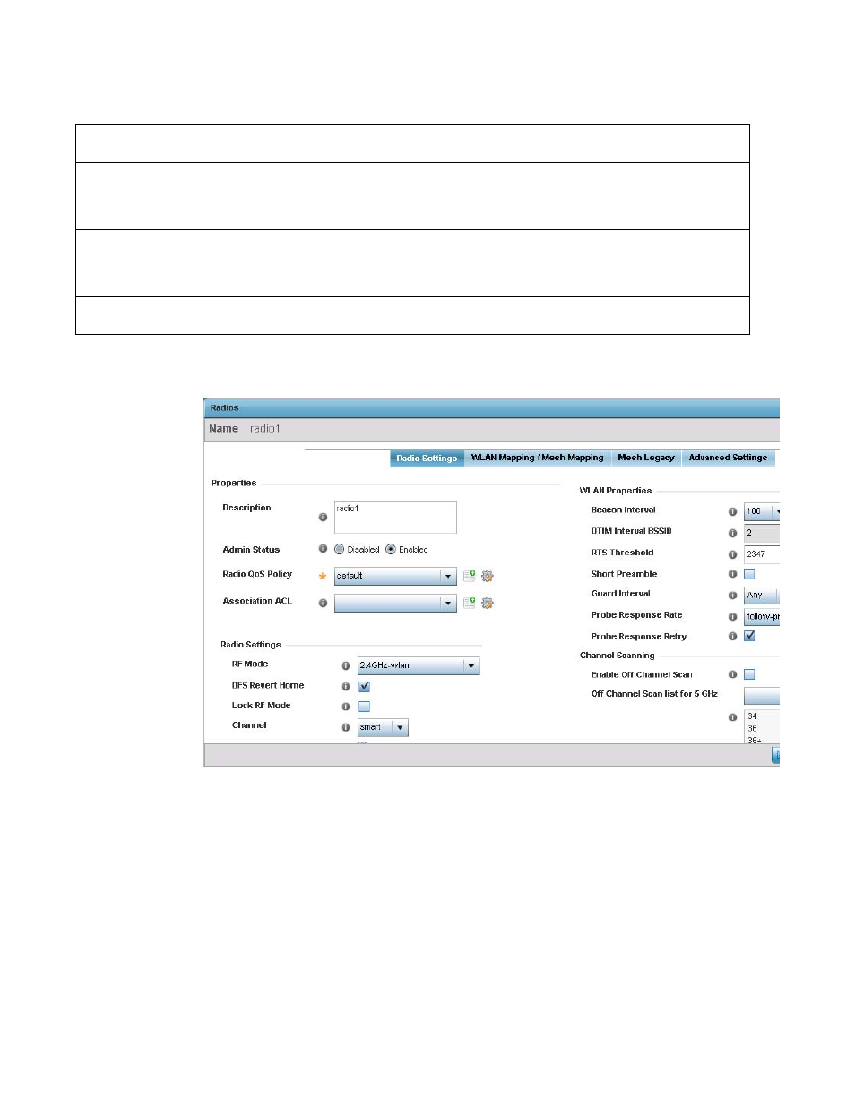
6. If required, select a radio configuration and select the Edit button to modify the radio
configuration.
FIGURE 24
Access Point Radio - Radio Settings tab
7. The Radio Settings tab displays by default.
Admin Status
A red “X” defines the radio’s status as currently disabled. A green check mark designates the
status as enabled.
RF Mode
Displays whether each listed radio is operating in the 802.11a/n or 802.11b/g/n radio band. If the
radio is a dedicated sensor, it will be listed as a sensor to define the radio as not providing typical
WLAN support. If the radio is a client-bridge, it will be listed as a client bridge and does not provide
typical WLAN support. The radio band is set from within the Radio Settings tab.
Channel
Lists the channel setting for the radio. Smart is the default setting. If set to Smart, the access point
scans non-overlapping channels listening for beacons from other access points. After the channels
are scanned, it selects the channel with the fewest access points. In the case of multiple access
points on the same channel, it will select the channel with the lowest average power level.
Transmit Power
Lists the transmit power for each radio. The column displays smart if set for dynamic Smart RF
support.