2 functions of devices in dvp-plc – Delta Electronics Programmable Logic Controller DVP-PLC User Manual
Page 99
2 Functions of Devices in DVP-PLC
DVP-PLC Application Manual
2-71
When the data backup memory card is installed in EH/EH2 MPU, MPU will operate according to the On/Off of switch
on the card. If the switch is “On”, the following comparisons will be conducted and the card will be copied to MPU. If
the switch is “Off”, MPU will not perform any action.
1. M1005 = On: An error occurs in the comparison between the ciphers of MPU and the data backup memory card
and MPU does not perform any action.
2. M1006 = On: The data backup memory card has not been initialized.
3. M1007 = On: Data in the program area of the data backup memory card do not exist, it means data doesn’t exist
in the program area of data backup memory card.
Function Group
Scan Time-out Timer
Number
M1008, D1008
Contents:
1.
M1008 = On: Scan time-out occurs during the execution of the program, and PLC ERROR LED indicator
remains beaconing.
2.
Users can use WPLSoft or HPP to monitor the content (STEP address when WDT timer is “On”).
Function Group
Checking Lost PLC SRAM Data
Number
D1009, M1175, M1176
Contents:
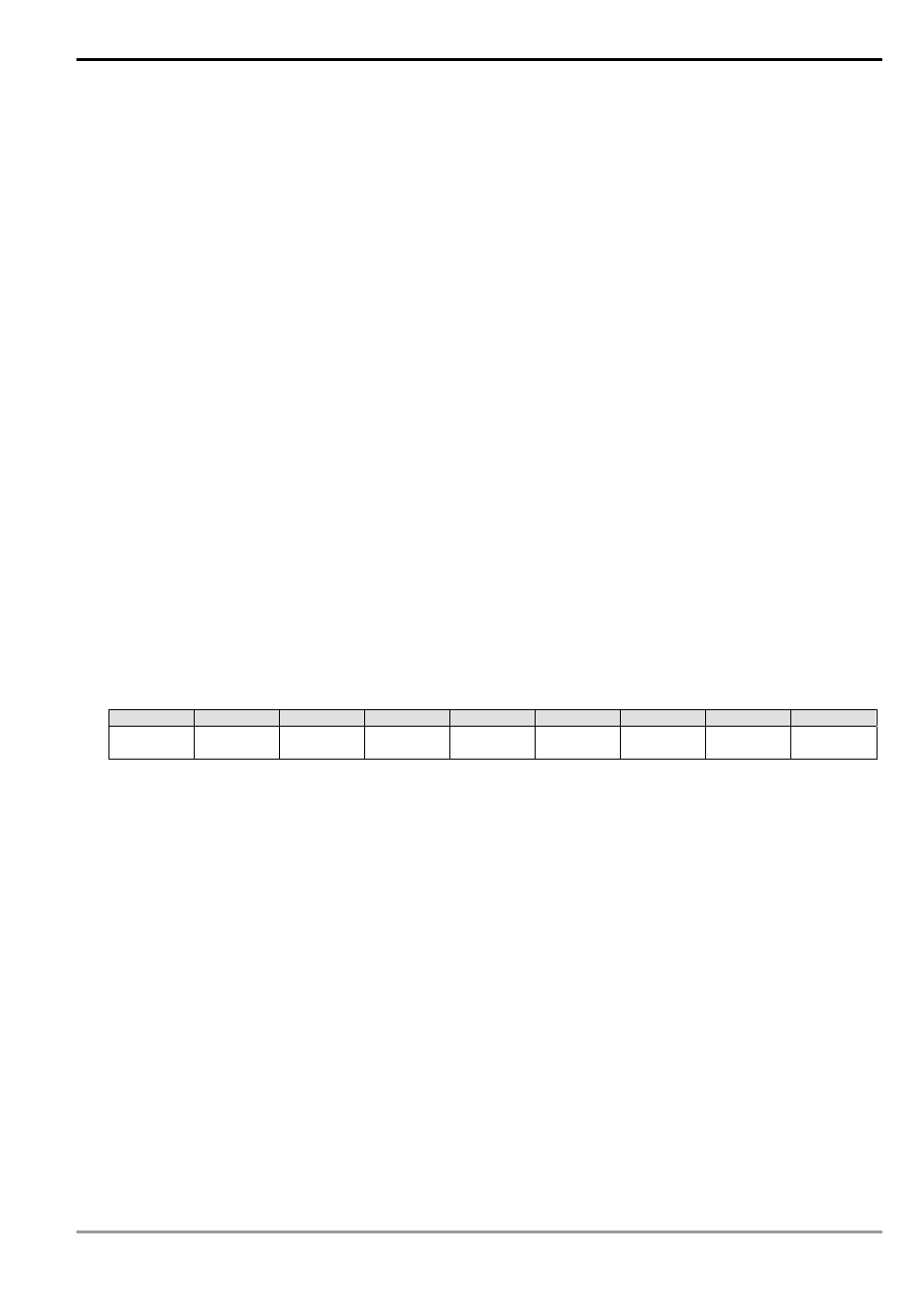
1. bit0 ~ bit7 record the types of data lost. bit = 1 refers to losing data; bit = 0 refers to correct data.
2. What are lost
bit8 ~ 15
bit 7
bit 6
bit 5
bit 4
bit 3
bit 2
bit 1
bit 0
Reserved
PLC
program
D register
T register
C register
File
register
M relay
S step
password
3. After the PLC is powered, the data in SRAM will be verified. If the SRAM data are lost, the PLC will record the
error in D1009 and set on M1175 or M1176 according to the content of the data.
Function Group
Scan Time Monitor
Number
D1010 ~ D1012
Contents:
The present value, minimum value and maximum value of scan time are stored in D1010 ~ D1012.
1. D1010: Present scan time value
2. D1011: Minimum scan time value
3. D1012: Maximum scan time value
Function Group
Internal Clock Pulse
Number
M1011 ~ M1014
Contents: