1 basic principles of plc ladder diagram – Delta Electronics Programmable Logic Controller DVP-PLC User Manual
Page 8
1 Basic Principles of PLC Ladder Diagram
DVP-PLC Application Manual
1-4
the ladder diagram come from the frequently-seen electromechanical devices, e.g. buttons, switches, relay, timer and
counter, etc. in the traditional power panel for automation control.
Internal devices in the PLC: The types and quantity of the devices in the PLC vary in different brand names.
Though the internal devices in the PLC adopts the names, e.g. transistor, coil, contact and so on, in the traditional
electric control circuit, these physical devices do not actually exist inside the PLC. There are only the corresponding
basic units (1 bit) inside the memory of the PLC. When the bit is “1”, the coil will be On, and when the bit is “0”, the coil
will be Off. The normally open contact (NO or contact A) directly reads the value of the corresponding bit. The
normally close contact (NC or contact B) reads the opposite state of the value of the corresponding bit. Many relays
will occupy many bits. 8 bits equal a “byte”. 2 bytes construct a “word” and 2 words combined is “double word”. Byte,
word or double words are used when many relays are processed (e.g. addition/subtraction, displacement) at the
same time. The other two devices, timer and counter, in the PLC have coil, timer value and counter value and they
have to process some values in byte, word or double word.
All kinds of internal devices in the value storage area in the PLC occupy their fixed amount of storage units.
When you use these devices, you are actually read the contents stored in the form of bit, byte or word.
Introductions on the basic internal devices in the PLC (See Ch 2. Functions of Devices in DVP-PLC for more details.)
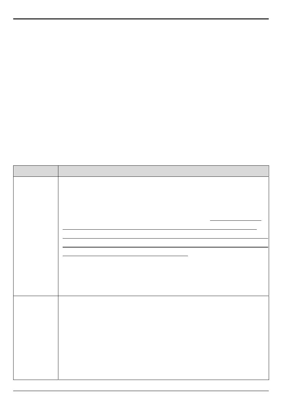
Device
Functions
Input relay
The input relay is an internal memory (storage) unit in the PLC corresponding to a external
input point and is used for connecting to the external input switches and receiving external
input signals. The input relay will be driven by the external input signals which make it “0” or
“1". Program designing cannot modify the status of the relay, i.e. it cannot re-write the basic
unit of a relay, nor can it force On/Off of the relay by HPP/WPLSoft. SA/SX/SC/EH/EH2/SV
series MPU can simulate input relay X and force On/Off of the relay. But the status of the
external input points will be updated and disabled, i.e. the external input signals will not be read
into their corresponding memories inside PLC, but only the input points on the MPU. The input
points on the extension modules will still operate normally. There are no limitations on the times
of using contact A and contact B of the input relay. The input relays without corresponding input
signals can only be left unused and cannot be used for other purposes.
&
Device indication: X0, X1,…X7, X10, X11,… are indicated as X and numbered in octal
form. The No. of input points are marked on MPU and extension modules.
Output relay
The output relay is an internal memory (storage) unit in the PLC corresponding to a external
output point and is used for connecting to the external load. The output relay will be driven by
the contact of an input relay, contacts of other internal devices and the contacts on itself. A
normally open contact of the output relay is connected to the external load. Same as the input
contacts, there are no limitations on the times of using other contacts of the output relay. The
output relay without corresponding output signals can only be left unused and can be used as
input relay if necessary.
&
Device indication: Y0, Y1,…Y7, Y10, Y11,…are indicated as Y and numbered in octal
form. The No. of output points are marked on MPU and extension modules.