Delta Electronics Programmable Logic Controller DVP-PLC User Manual
Page 394
7 Application Instructions API 50-99
D V P - P L C A P P L I C AT I O N M A N U A L
7-110
11. The explanation of 32-bit S
3
and 16-bit S
3
are almost the same. The difference is the capacity of S
3
+5 ~ S
3
+20.
PID Equations:
1. The PID operation is conducted according to the speed and the differential PV.
2. The PID operation has three control directions: automatic, foreward and inverse. Forward or inverse are
designated in S
3
+4. Other relevant settings of PID operation are set by the registers designated in S
3
~ S
3
+ 5.
3. Basic PID equation:
( )
( )
( )
S
t
PV
K
S
t
E
K
t
E
K
MV
D
I
P
*
1
*
*
+
+
=
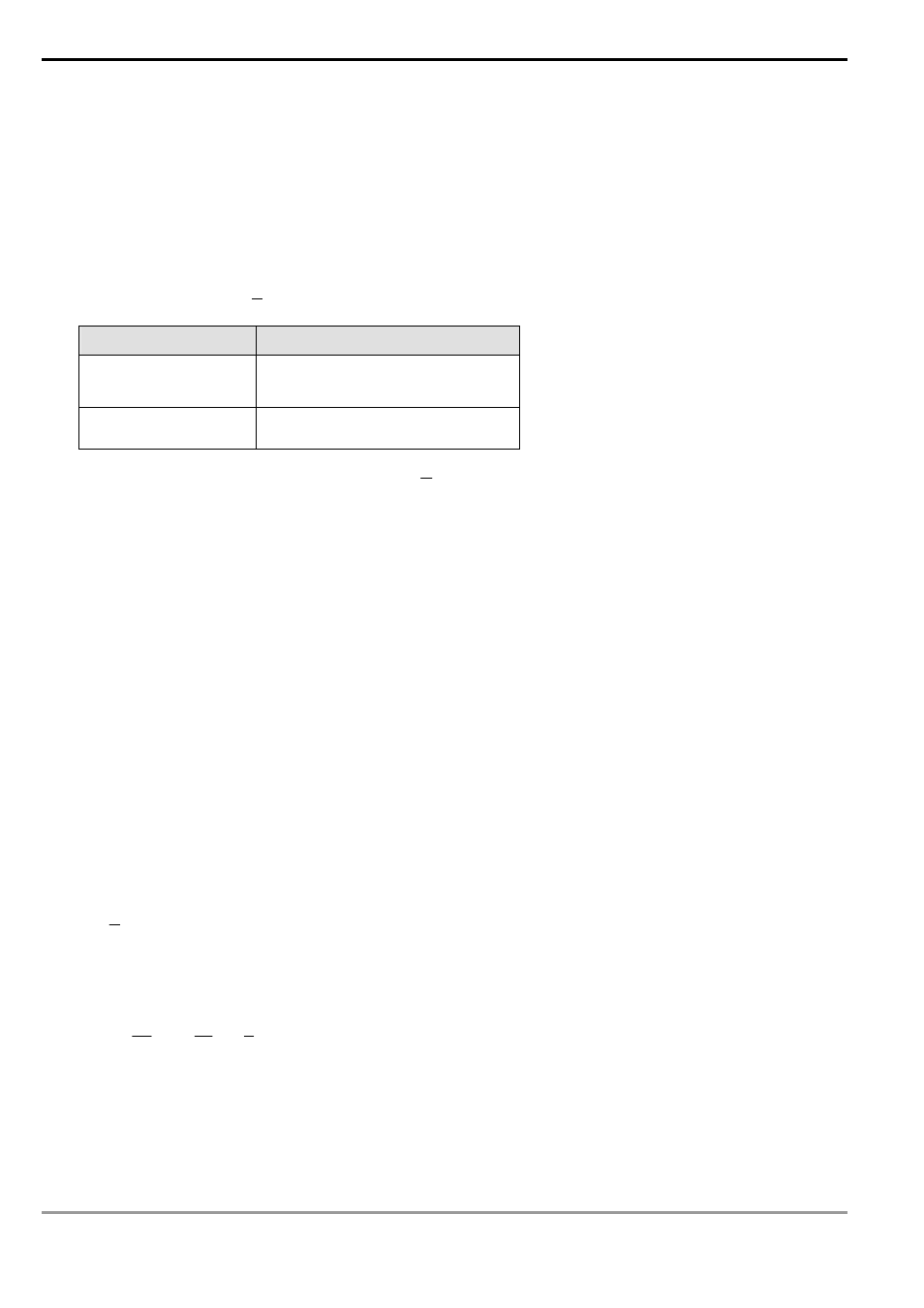
Control direction
PID equation
Forward, automatic
E(t) = SV – PV
Inverse
E(t) = PV – SV
( )
S
t
PV
is the differential value of
( )
t
PV
;
( )
S
t
E
1 is the integral value of
( )
t
E
. When
( )
t
E
is less than 0
as the control direction is selected as forward or inverse, ( )
t
E
will be regarded as “0".
The equation above illustrates that this instruction is different from a general PID instruction by the variable use
of the differential value. To avoid the flaw that the transient differential value is too big when a general PID
instruction is executed for the first time, our PID instruction monitors the differentiation status of the PV. When
the variation of PV is too big, this instruction will reduce the output of MV.
4. Symbol
explanation:
MV
: Output value
P
K
: Proprotional gain
( )
t
E
: Error value
PV
: Present measured value
SV
: Target value
D
K : Differential gain
( )
S
t
PV
: Differential value of PV(t)
I
K : Integral gain
( )
S
t
E
1
: Integral value of E(t)
5. Temperature
Control
Equation:
When S
3
+4 is K3 and K4, the equation used in diagram 2 (see below) will be changed as:
( )
( )
( )
⎥
⎦
⎤
⎢
⎣
⎡
+
⎟
⎠
⎞
⎜
⎝
⎛
+
=
S
t
PV
K
S
t
E
K
t
E
K
MV
D
I
P
*
1
1
1
In which the error value is fixed as E(t) = SV – PV
This equation is exclusively designed for temperature control. Therefore, when the sampling time (T
S
) is set as 4
seconds (K400), the range of output value (MV) will be K0 ~ K4,000 and the cycle time of GPWM instruction
used together has to be set as 4 seconds (K4000) as well.