Delta Electronics Programmable Logic Controller DVP-PLC User Manual
Page 523
9 Application Instructions API 150-199
DVP-PLC Application Manual
9-51
API Mnemonic
Operands
Function
172
D ADDR P
Floating Point Addition
Controllers
ES/EX/SS SA/SX/SC EH/SV
Bit Devices
Word Devices
Program Steps
Type
OP
X Y M S K H
KnX KnY KnM KnS T
C
D
E
F
S
1
*
S
2
*
D
*
DADDR, DADDRP: 13 steps
PULSE 16-bit 32-bit
ES EX SS SA SX SC EH SV ES EX SS SA SX SC EH SV ES EX SS SA SX SC EH SV
Operands:
S
1
: Floating point summand S
2
: Floating point addend D: Sum
Explanations:
1. S
1
and S
2
can be floating point values (FX.XX).
2. See the specifications of each model for their range of use.
3. Flags: M1020 (zero flag), M1021 (borrow flag), M1022 (carry flag)
4. In DADDR instruction, floating point values (e.g. F1.2) can be entered directly into S
1
and S
2
or stored in register
D for operation. When the instruction is being executed, operand D will store the operation result.
5. When
S
1
and S
2
stores the floating point values in register D, their functions are the same as API 120 EADD.
6. S
1
and S
2
can designate the same register. In this case, if the “continuous execution” type instruction is in use and
during the On period of the drive contact, the register will be added once in every scan by a “pulse execution” type
instruction (DADDRP).
7. If the absolute value of the operation result is larger than the maximum floating point displayable, the carry flag
M1022 will be On.
8. If the absolute value of the operation result is smaller than the minimum floating point displayable, the borrow flag
M1021 will be On.
9. If the operation result is “0”, the zero flag M1020 will be On.
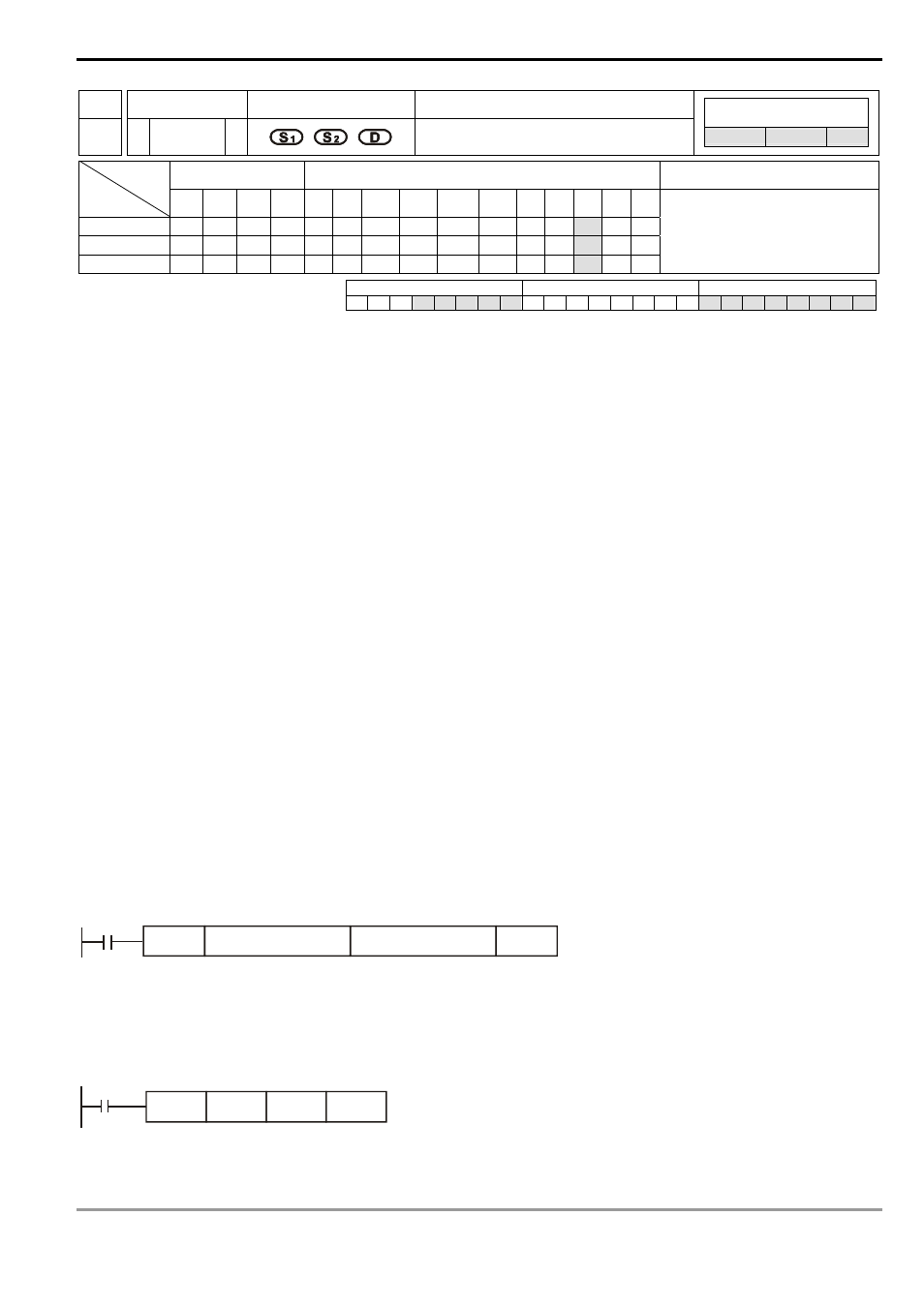
Program Example 1:
When X0 = On, the floating point F1.20000004768372 will plus F2.20000004768372 and the result
F3.40000009536743 will be stored in the data registers (D10, D11).
X0
DA DDR
F1.20000004768372
D10
F1.20000004768372
F2.20000004768372
Program Example 2:
When X0 = On, the floating point value (D1, D0) + floating point value (D3, D2) and the result will be stored in the
registers designated in (D11, D10).
X0
DADDR
D0
D2
D10