Delta Electronics Programmable Logic Controller DVP-PLC User Manual
Page 357
7 Application Instructions API 50-99
D V P - P L C A P P L I C AT I O N M A N U A L
7-73
API Mnemonic
Operands
Function
77
PR
Print (ASCII Code Output)
Controllers
ES/EX/SS SA/SX/SC EH/SV
Bit Devices
Word Devices
Program Steps
Type
OP
X Y M S K H
KnX KnY KnM KnS T
C
D
E
F
S
*
*
*
D
*
PR: 5 steps
PULSE 16-bit 32-bit
ES EX SS SA SX SC EH SV ES EX SS SA SX SC EH SV ES EX SS SA SX SC EH SV
Operands:
S
: Device for storing ASCII code D: External ASCII code output points
Explanations:
1. S will occupy 4 consecutive points.
2. D will occupy 10 consecutive points.
3. This instruction can only be used twice in the program.
4. See the specifications of each model for their range of use.
5. Flags: M1029 (PR execution completed); M1027 (number of PR outputs)
6. This instruction will output the ASCII codes in the 4 registers starting from S from the output devices in the order
designated in D.
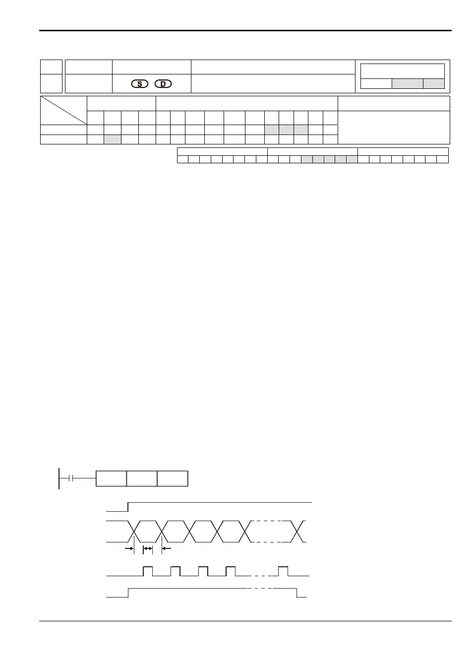
Program Example 1:
1. Use API 76 ASC to convert A ~ H into ASCII codes and store them in D0 ~ D3 and use this instruction to output
the codes in sequence.
2. When M1027 = Off and X10 goes On, the instruction will be executed. Designate Y10 (low bits) ~ Y17 (high bits)
as the data output points and Y20 for scan signals. Designate Y21 for the monitor signals during the execution.
In this mode, you can execute an output for 8 letters in sequence. During the output, if the drive contact goes Off,
the data output will stop immediately and all the outputs will go Off.
3. During the execution of the instruction, when X10 goes Off, all the data output will be interrupted. When X10 is
On again, the output will be restarted.
X10
PR
D0
Y10
T T T
A B C D
H
X10 start signal
Y10 ~ Y17 data
Y20 scan signal
Y21 being executed
T: scan time (ms)