1 basic principles of plc ladder diagram – Delta Electronics Programmable Logic Controller DVP-PLC User Manual
Page 25
1 Basic Principles of PLC Ladder Diagram
DVP-PLC Application Manual
1-21
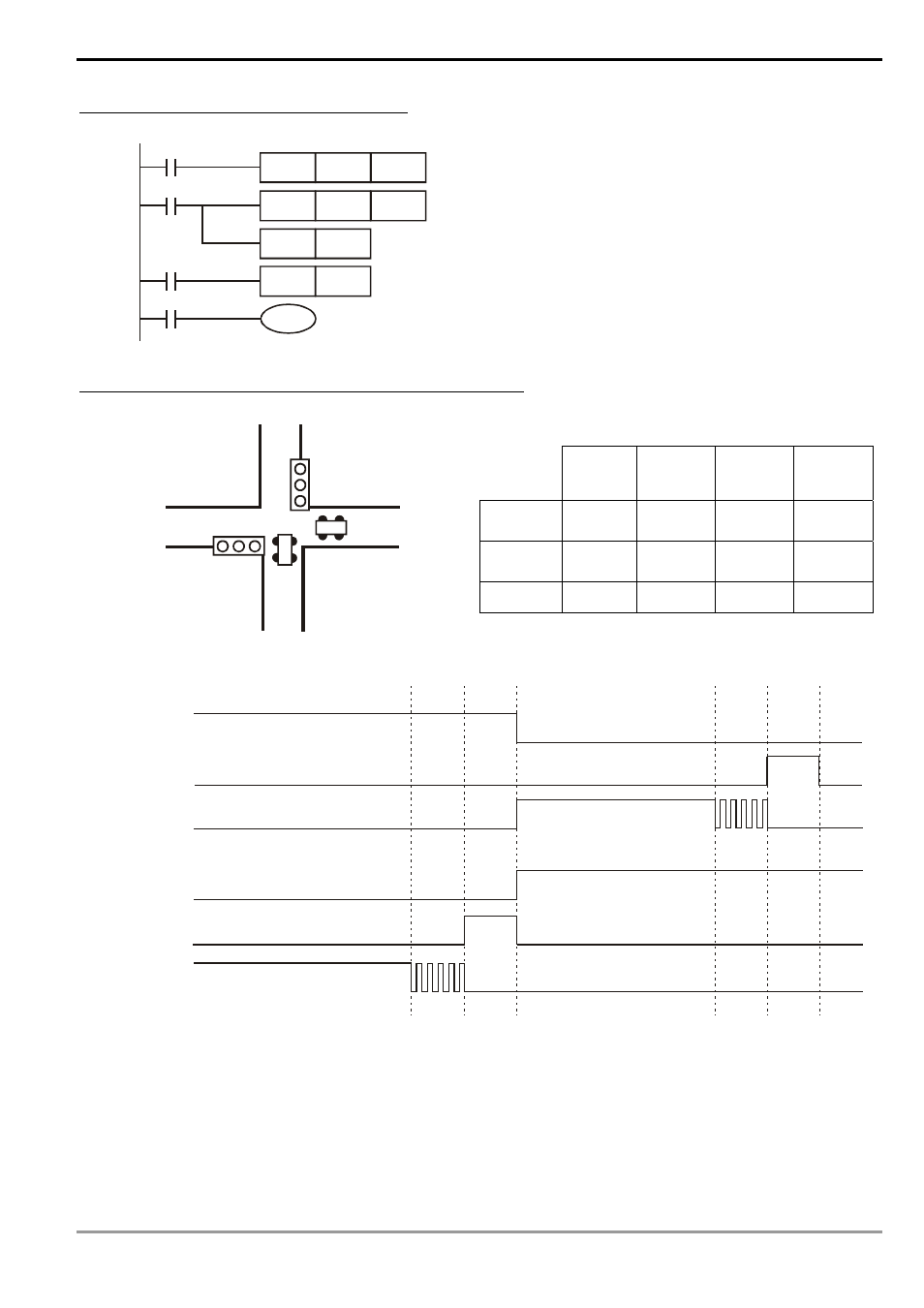
Example 14: How to enlarge the counting range
C6
CNT
Kn2
C5
X13
CNT
RST
C5
Kn1
X14
C5
RST
Y1
C6
C6
The counting range of a 16-bit counter is 0 ~ 32,767. As
the circuit in the left hand side, using two counters can
increase the counting range to n1*n2. When the counting
of counter C5 reaches n1, C6 will start to count for one
time and reset for counting the pulses from X13. When
the counting of counter C6 reaches n2, the pulses from
input X13 will be n1*n2.
Example 15: Traffic light control (by using step ladder instruction)
Vertical
Light
Horizontal
Light
Traffic light control
Red
light
Yellow
light
Green
light
Green
light
flashes
Vertical
light
Y0 Y1 Y2 Y2
Horizontal
light
Y10 Y11 Y12 Y12
On time
35 secs
5 secs
25 secs
5 secs
Timing Diagram:
Y0
Y1
Y2
Y10
Y11
Y12
Vertical
Light
Red
Yellow
Green
Horizontal
Light
Red
Yellow
Green
25 secs
5 secs
5 secs
25 secs
5 secs
5 secs
- 1x9 Bi-Directional Transceiver Module OPBD-155F2J1R (7 pages)
- Single Mode SFP Transceiver LCP-1250B4MDRx (14 pages)
- LC-1250xxxx Series (10 pages)
- Human Machine Interface DOP-AS Series (329 pages)
- Analog Output Module DVP04DA-S (2 pages)
- DeviceNet Slave Communication Module IFD9502 (2 pages)
- LCP-155B4MSRx (12 pages)
- High-Speed PCI 12-Axis Motion Control Card PCI-DMC-B01 (528 pages)
- Network Device DVP01PU-S (2 pages)
- GBIC-1250D5MR (12 pages)
- SPBD-1250A4Q1RT (10 pages)
- SILM4015 (1 page)
- LCP-8500A4EDR (14 pages)
- 10GBASE-SR SFP+ Optical Transceiver LCP-10G3A4EDR (16 pages)
- LCP-155A4HSRx (11 pages)
- LCP-1250RJ3SR-L (9 pages)
- SILM320L (1 page)
- LCP-1250RJ3SR-S (9 pages)
- SIL530 (1 page)
- Extension Digital I/O Module DOP-EXIO28RAE (1 page)
- DVP Series PLC DVP04TC-H2 (2 pages)
- 1x9 Bi-Directional Transceiver Module OPBD-155F1J1R (7 pages)
- Distribution Box TAP-CN01/02/03 (2 pages)
- LCP-200A4HSR (9 pages)
- Pulse Generation Unit DVP01PU-H2 (2 pages)
- Power Connection Interface VFD-PSD01 (1 page)
- Programmable Logic Controller DVP04DA-H2 (2 pages)
- Single Mode SFP Transceiver LCP-1250B4QDRx (13 pages)
- LCP-155B4JSRx Series (12 pages)
- Series Temperature Controller DTD Series (2 pages)
- Brake Modules BUE Series (2 pages)
- PLC DVP Series DVP-SX (2 pages)
- Digital Keypad / Display ASD-PU-01A (1 page)
- Multimode SFP Transceiver LCP-1250A4FDRx (14 pages)
- HMU1362M (1 page)
- RPA-01 (1 page)
- THMR1395 (1 page)
- SFBD-155F2J1RM (7 pages)
- Program Transfer Module DVP-PCC01 (1 page)
- RTU-DNET (41 pages)
- AC Servo Drive ASDA-AB (37 pages)
- Digital Keypad / Display ASD-PU-01B (1 page)
- HMR1045 (1 page)
- CANopen Communication Module DVPCOPM-SL (2 pages)
- SPBD-1250B4Q1R (10 pages)